Learn the Pneumatic Press Machine operation with Siemens PLC and the wiring of PLC with push buttons, proximity sensors, and solenoid valves.
Introduction to Pneumatic Press Operation
Pressing operations are a familiar process in the manufacturing field. Starting from small bushes to large stampings for the electrical machines is done by press operations only.
The Pneumatic Press machine operates with safety interlocks and an automatic process, so that we can do the process without getting any incidents and automation increases the efficiency of the process.
Many industries follow preventive actions for reducing the incidents on the machine and also the accidents to the operators. Our process uses compressed air for the pressing operation & with the help of proximity sensors, safety measures were implemented. And the operations were controlled and executed by Siemens PLC.
Components of Press Machine
The main components are mentioned below.
- PLC
- Compressor
- 5/2 Directional valve
- Flow Control Valve
- Proximity Sensor
- Double Acting Cylinder
- Push Buttons
PLC
PLC is the controller for the press machine. PLC gets the inputs from the process and executes the logic which gives the necessary output.
For our PLC project, we used Siemens Simatic S7-1200 PLC.
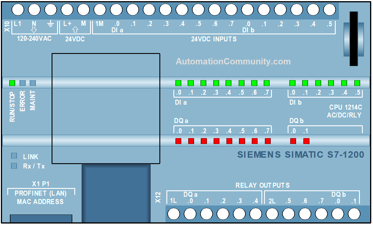
This PLC works with a 24 V DC power supply with 15 inputs and 10 outputs. Input works with 24 V DC and outputs are relay type.
In this machine, we connect 4 inputs for input control and 6 relay coils for output logic.
Compressor
The compressor is the power source for the pneumatic system. The compressor is used to increase the pressure of air. Normal atmospheric air will not be sufficient to move the components, since it is not pressurized.
For this purpose, the compressor is used for increasing the pressure of the air. The compressor takes air from the atmosphere and compresses it to increase the pressure and then sent to the system for performing the operation. Normally, the pressurized air denotes in the units such as bar or psi. For our system, we are using 5 Bar pressure for the process.
5/2 Directional Control Valve
The directional Control Valve (DCV) in the pneumatic system is used to control the movement of the compressed air. The DCV shifts the direction depending on the control signal.
Here 5/2 indicates 5 ports and 2 switching positions. In the 5 ports, 1 port is used for input supply, 2 ports for the output signal, and the other 2 ports for exhaust.
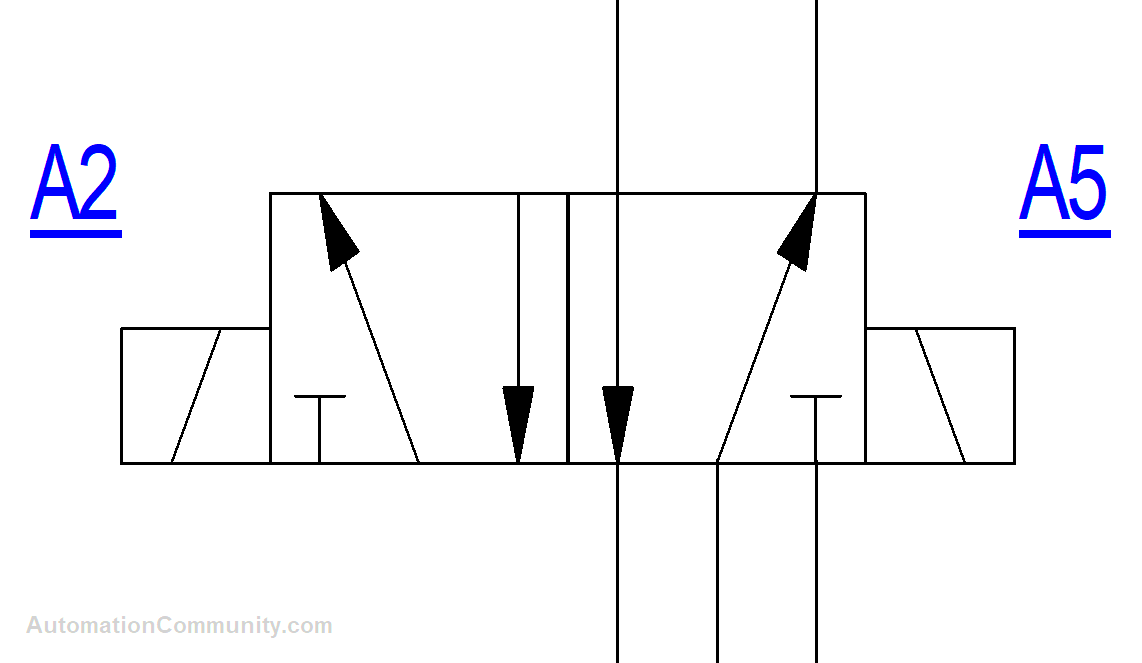
This is the same for the two switching positions. This connects before the actuators, from this only the signal moves to the actuators for performing the operation.
There were many methods for the mode of switching positions like mechanical, manual, pilot, and electrical. For our process, we used Electrical mode i.e., solenoid actuation.
Flow Control Valve
The flow control valve is used to reduce the flow of the compressed air enters into the actuators. It adjusts the flow of the system which gives the necessary force to the actuator.
There is a knob at the top of the valve which is used to adjust the flow.
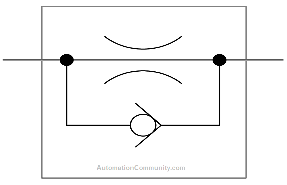
In our process, we used one flow control valve in the pressing cylinder since pressing wants to be done with minimal speed so that the product or components will not get damaged.
Proximity Sensors
The proximity sensor is used to detect the presence of an object without making the contact. Inductive, capacitive, and photoelectric were some of the types of proximity sensors.
Depending on the application we can choose any of the types of proximity sensors. For our pressing machine, we used inductive proximity sensors for detecting metallic objects.
Double Acting Cylinder
Cylinders are one of the actuators in pneumatic systems. A double-acting cylinder is the most used cylinder-type actuator in industries nowadays.
Double acting represents it has controllable forward and reverse movements.
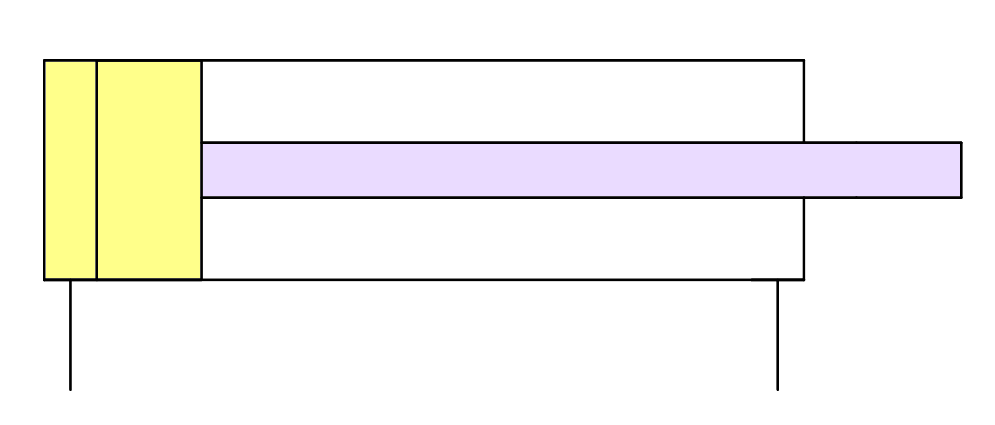
Two movements of the cylinders were controlled by the two ports. Ports are the passage where the compressed air gets entered and moves the piston of the cylinder for operation.
Push Button
Push Buttons are the control elements that are used to start or stop the process. The Pushbutton has two contacts, they are Normally Open contact and normally closed contact.
Normally open contact is mainly used in the start button and normally closed contact is mainly used in the stop push button.
We have used two normally open contacts for starting the main process of our project.
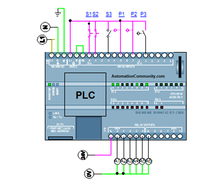
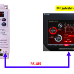
PLC Wiring of Pneumatic Press Machine
The pressing machine operation was totally controlled by the Siemens S7-1200 PLC. It operates with a 24V DC power supply.
4 inputs were used in this process. 1 push button and 3 proximity switches were used. These 4 were connected with inputs of address I0.0, I0.5, I0.7, and I1.1.
The outputs are connected with relay outputs, the output PLC addresses are Q0.0 to Q0.5.
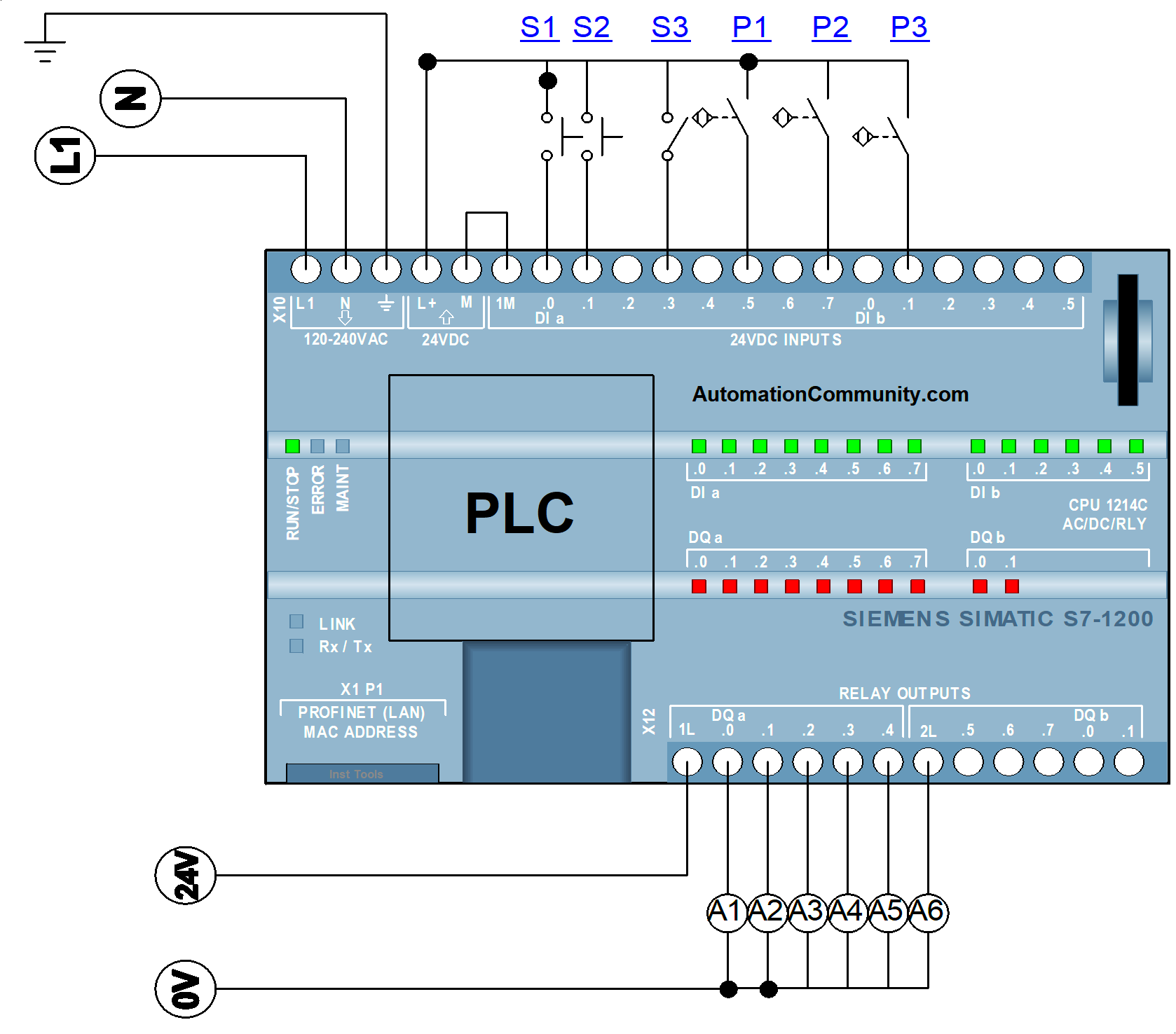
When Push button S1 is pressed it gives signals to I0.0, similarly, Proximity sensors P1, P2, and P3 will give signals to I0.5, I0.7, and I1.1. These inputs will process and the PLC sends the signal to the relay coils A1 to A6 as per the PLC logic mentioned in the program.
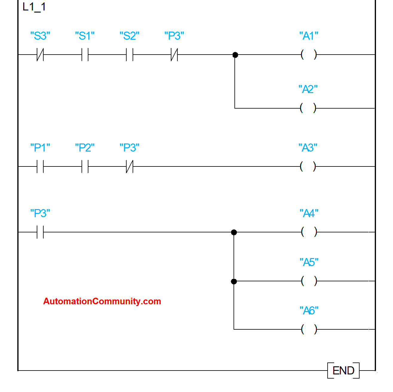
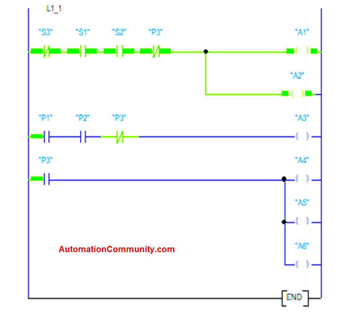
PLC Ladder Logic of Press Machine
PLC ladder logic describes the function of the machine application. Depending on the logic uploaded in the PLC, the process will be executed.
All the inputs and outputs connected in the PLC need to be mentioned in the logic, by this only all the things are executed in the machine. The wrong program will lead to the wrong function in the process & it may not results in the desired output.
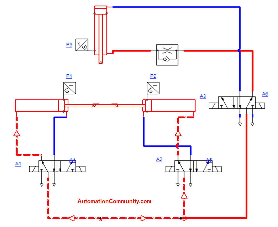
Pneumatic Circuit
The pneumatic circuit executes the final process with the help of components like double-acting cylinders, a 5/2 Direction control valve, proximity sensors, a flow control valve, and the energy source compressor.
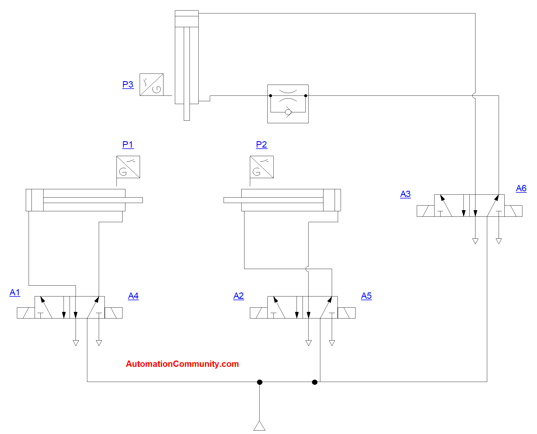
All the components are connected through the air lines (air hoses) which act as a passage for the movement. This circuit executes with a pressure of 5 bar.
The direction control valve has the actuating method of the solenoid which controls the movement of the spools inside.
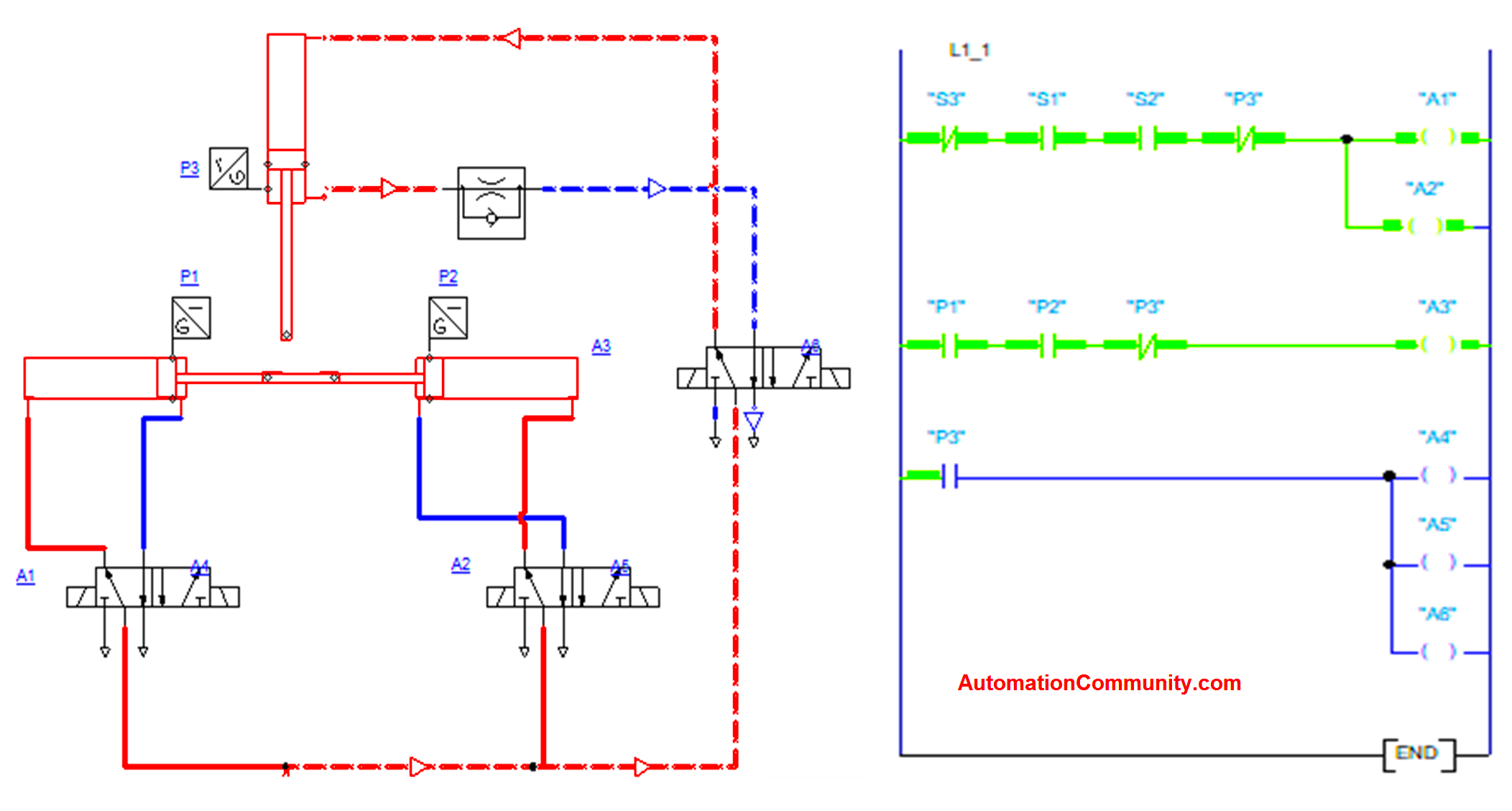
Pneumatic Press Machine Working Principle
Compressed air supply of 5 bar is given to the pneumatic system. All the cylinders are in the default position.
Whenever the Pushbutton S1 and S2 have pressed then the process starts. This activates the inputs of the PLC and as per the PLC programming, the relays A1 and A2 were activated.
These relays activate the solenoid of the directional control valves which activates the Cylinder 1 and Cylinder 2 to move forward. Cylinder 1 and Cylinder 2 were door of the pressing machine.
Once both Cylinder 1 and Cylinder 2 get closed. The end position of the cylinders was sensed by the proximity sensors.
The next process will start only if we get a signal from both proximity sensors. Considering the safety principle, we are using the PLC logic to identify the signal status from the proximity sensors.
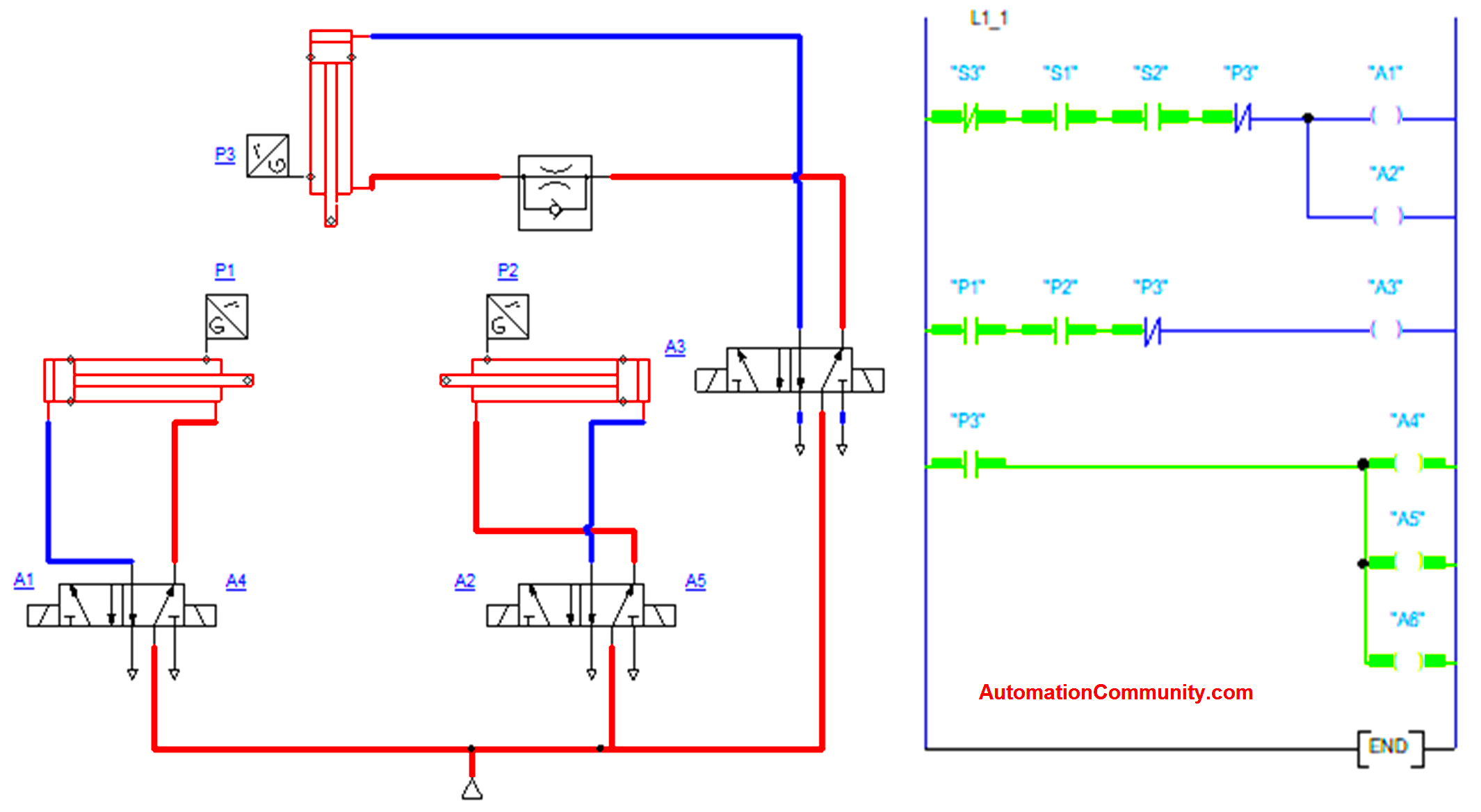
After the signals of the proximity sensor are received, pressing operation will start. This was executed by another pneumatic cylinder.
Sensor signals make the relay A3 to activate which makes the solenoid valve to direct the cylinder. The cylinder moves slowly compared to the regular force with the help of the Flow control valve.
Flow control valves reduce the force of the cylinder by reducing the volume with the help of a throttle valve. Depending on the components to be pressed, the valve will be adjusted, similarly, the force also gets adjusted.
The pressing cylinder’s end position is also sensed by the proximity sensor. This proximity sensor defines the exact distance the cylinder needs to be moved.
If the cylinder gets the end position, the proximity sensor activates the relays A4, A5, and A6. This will make all three cylinders move back to their home/default position and complete one cycle. The cycle will get repeated by pressing the start buttons S1 and S2 again.
If we want to stop the process in between means, S3 needs to be pressed for stopping the process at any time while executing.
If S3 is activated before the process means the whole process will not get started as it acts as an emergency stop button. This is also one of the safety measures used in this process.
PLC Simulation
Watch the below video for the simulation of a pneumatic press machine.
Conclusion
The press machine operation is mainly used in industries for combining two components in mechanical workshops. We used a combination of pneumatic systems and PLC for performing these operations safely. Also, we used some preventive interlocks for the protection of the machines and personnel.
Read Next:
Sukumar
April 1, 2023Great Article. One thing is that 2L to be connected with 24V DC and next channel to be used for the A6 output.
K.Mugunthan
April 1, 2023Hi Sukumar,
I m the author of this article
Yes that’s a mistake, I wrongly connected in that channel. Thanks for your feedback
Suresh
April 5, 2023Thank you. If please explain the logic in the video.
RAVI JOSHI
April 11, 2023Hello Muguntan. Regarding the Flow control valve: The symbol of the Flow control valve should have an ARROW on the orifice to adjust the flow and speed of pressing the cylinder as per your explanation.