By using this site, you agree to the Privacy Policy and Terms of Use.
Accept
Automation CommunityAutomation Community
  • PLC
  • Control Systems
  • Instrumentation
  • Calibration
  • Electrical
  • Courses
    • Siemens PLC Course
    • Allen Bradley PLC Course
    • InTouch SCADA Course
    • WinCC SCADA Course
    • Siemens Tia Portal
    • Omron PLC Course
    • Advanced PLC Course
Search
  • Customize Interests
  • My Bookmarks
© Automation Community. All Rights Reserved.
Reading: PLC Program for Welding Arm Robot Wire and Gas Consumption Calculation
Share
Notification Show More
Aa
Automation CommunityAutomation Community
Aa
  • PLC
  • Control Systems
  • Instrumentation
Search
  • PLC
  • Control Systems
  • Instrumentation
  • Calibration
  • Electrical
  • Courses
    • Siemens PLC Course
    • Allen Bradley PLC Course
    • InTouch SCADA Course
    • WinCC SCADA Course
    • Siemens Tia Portal
    • Omron PLC Course
    • Advanced PLC Course
Follow US
© 2023. All Rights Reserved.
Automation Community > Blog > PLC > PLC Program for Welding Arm Robot Wire and Gas Consumption Calculation
PLC

PLC Program for Welding Arm Robot Wire and Gas Consumption Calculation

Sharique Anwar
Last updated: 2023/04/29 at 7:27 AM
Sharique Anwar
Share
6 Min Read
SHARE

In this article, we will learn the PLC program for welding arm robot wire and gas consumption in grams and in liters per second.

Contents
PLC Program for Welding Arm RobotLadder LogicConclusion

In this application, arm robots are used to perform Metal Inert Gas, or MIG, welding on an automotive part. Solid or flux-core welding wire, as well as a CO2 and argon gas combination, are used in this process.

Using a PLC, wire consumption in grams and gas consumption in liters per second have to be determined as required by the user. In this article, we will learn the PLC program for welding arm robots wire and gas consumption.

PLC Program for Welding Arm Robot

PLC Programming for Welding Robot

To do this, an encoder is installed inside the elbow joint section so that as the wire is drawn into the wire feeding tube, the encoder shaft rotates. Thus, the wire is measured using an encoder, and then its weight is calculated.

Through the Flow Transducer installed in the pipeline’s path, the gas is transported to the “Torch Travel” area.

Ladder Logic

The below program shows the PLC logic for the welding robot gas and wire consumption calculation part.
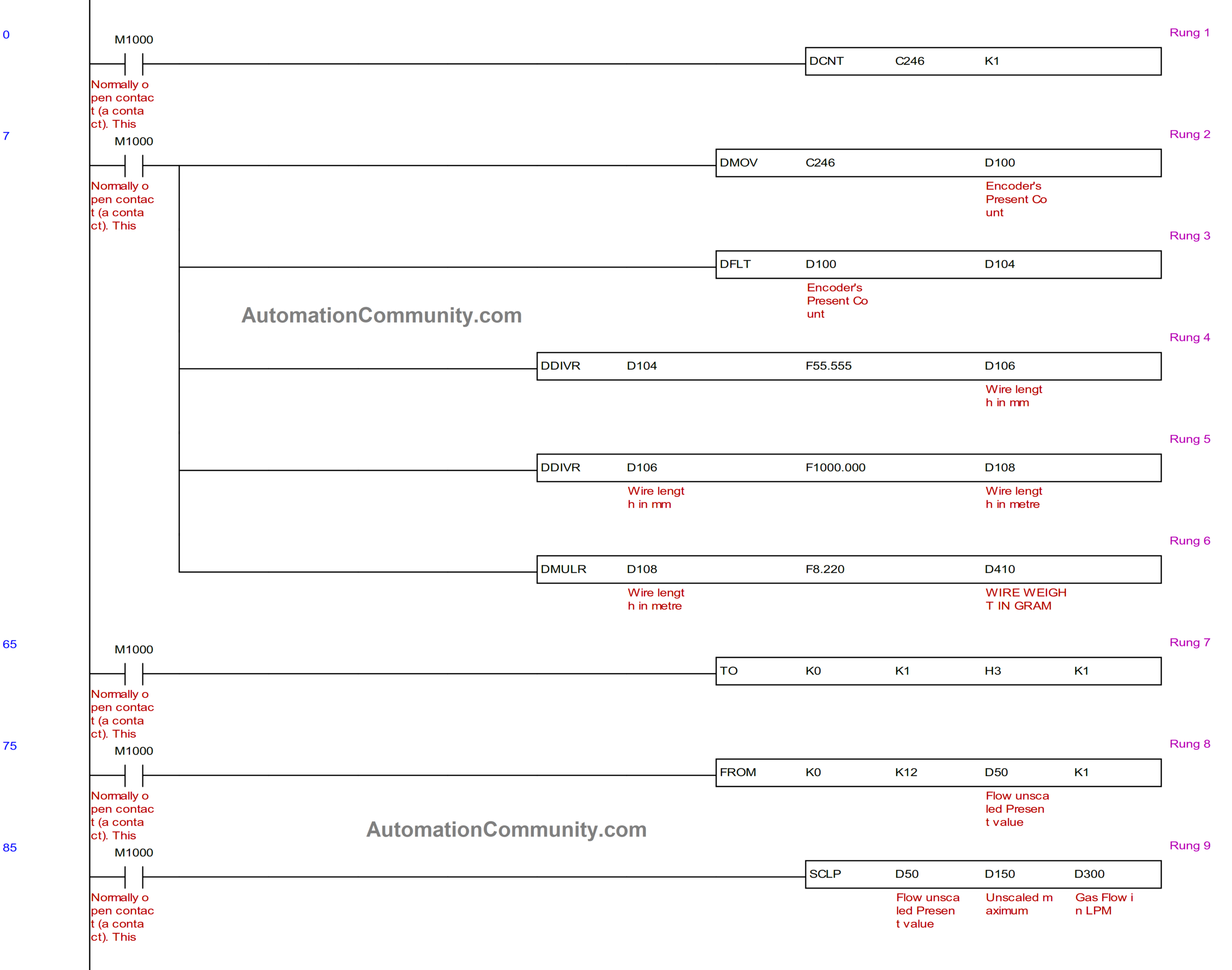
PLC Program for Welding Arm Robot

Rung 1

Encoder is set up using the PLC’s X0 and X1 inputs (which can only be used for encoders), and the high-speed counter’s counter no. 246 reads the encoder’s current count.

Rung 2 and 3

The current encoder count is initially recorded in D100 before being translated to float format and saved in D104.

Rung 4

Encoder produces a total of 5000 pulses per rotation. Each time the encoder turns by one revolution, it is physically measured that 90 mm of wire is taken out.

Applying the Unitary method, It takes around 55.55 pulses to draw out 1 mm.

The wire length in mm is then determined by dividing the pulses detected in D104 by 55.55. This data is stored in D106.

Rung 5

More Read

30 Communication Protocols in Automation and Instrumentation

RS232 RS485 RS422 Communication Protocols – Questions and Answers

Serial Communication Questions and Answers

Profibus Questions and Answers

Stepper Motor Questions and Answers

The total wire length calculated in millimeters is then converted into meters and stored in D108.

Rung 6

The weight of 1 mm of wire, as determined by physical measurement, is 8.22 grams. The total weight of the wire in grams is calculated using the unitary method by multiplying the whole wire length by 8.22. This weight is stored in D410.

Rung 7

A 4 to 20 mA signal from the flow transducer is received at one of the Analog input card’s Channels to calculate the gas flow rate.

The Analog Input Card’s input mode setting is defined by “TO K0 K1 H3 K1,” where H3 specifies that the first channel is set to mA signal mode.

Rung 8

The present decimal value on the first channel of the Analog Input module is read with the command “FROM K0 K12 D50 K1.” The value is stored in D50.

PLC Logic for Wire and Gas Consumption

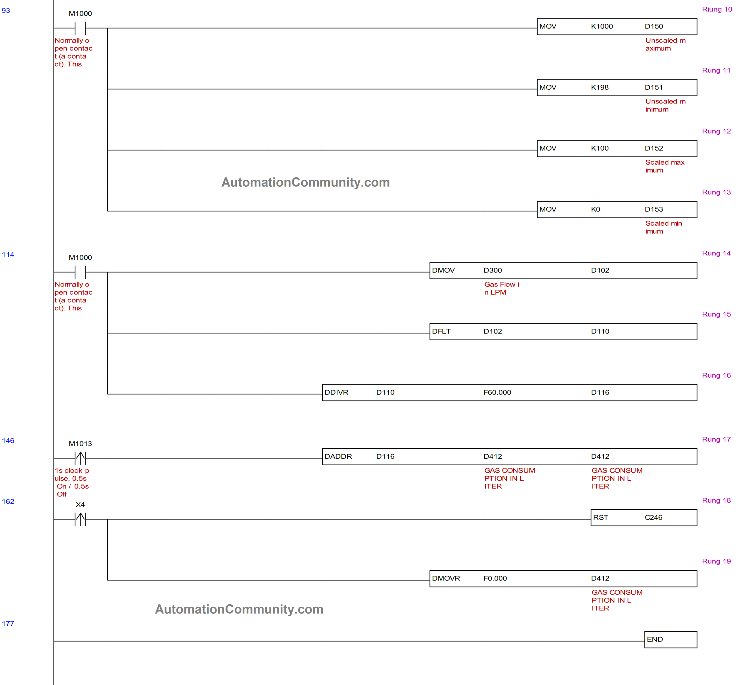
Rung 9, 10, 11, 12, and 13

The flow transducer shows the flow rate in liters per minute, ranging from 0 to 100. It generates a 4mA signal at 0 LPM and a 20mA signal at 100 LPM.

In this instance, the decimal value read at maximum flow is 1000, however, it is 198 at minimum or no flow. This value must be scaled into the appropriate unit, which is LPM.

D150 sets the maximum unscaled value, whereas D151 specifies the minimum unscaled value. D152 defines the maximum scale, whereas D153 defines the minimum scale.

Based on the constraints defined in D150 to D153, the SCLP instruction is used to produce the resulting scaled value in D300 with regard to the current unscaled decimal value read in D50. The unit of the value registered in D300 is liters per minute.

Rung 14, 15, and 16

D300’s value is transformed into float format and saved in D110.

The value is then divided by 60 to convert it to liters per second, and it is saved in D116.

Rung 17

Using an internal one-second clock pulse bit M1013, the value in D116 is then totaled in D412 once every second. Thus, D412 records total gas consumption in liters.

Rung 18, 19

The encoder counts and liters consumed are both reset to zero when the Reset button X4 is pushed.

Conclusion

To determine the weight of the wire and the number of liters used during welding, the encoder, and flow transducer are integrated with the welding robot.

Read Next:

  • HMI Screen Design
  • What is a Safety PLC?
  • RS232, RS422, RS485
  • Siemens Automation
  • PLC Hydraulic Clamping

You Might Also Like

Sensors and Transducers Objective Questions and Answers

Cybersecurity Questions and Answers

Electrical Switches Objective Questions and Answers

Programmable Logic Controller Questions and Answers – PLC

Fire Fighting Pump Room Monitoring System – PLC Project

TAGGED: PLC, PLC Example, PLC Logic, PLC Program, PLC Programming, PLC Projects, PLC Tutorials, Programmable Logic Controller, Welding Robot

Sign Up For Daily Newsletter

Be keep up! Get the latest breaking news delivered straight to your inbox.
[mc4wp_form]
By signing up, you agree to our Terms of Use and acknowledge the data practices in our Privacy Policy. You may unsubscribe at any time.
Share This Article
Facebook Twitter Whatsapp Whatsapp LinkedIn
Share
Previous Article Siemens Logo PLC Getting Started with Siemens Industrial Automation
Next Article Poka-Yoke Assembly Table PLC Programming for Poka-Yoke Assembly Table
1 Comment 1 Comment
  • Vivek says:
    April 6, 2023 at 11:20 am

    Thanks. Please provide complete program

    Reply

Leave a Reply Cancel reply

Your email address will not be published. Required fields are marked *

Stay Connected

120.5k Followers Like
10.1k Followers Follow
90.6k Subscribers Subscribe

Latest Articles

Orifice Plate
Orifice Plate Questions and Answers
Instrumentation June 5, 2023
Sensors and Transducers Objective Questions and Answers
Instrumentation Control Systems PLC June 4, 2023
Cybersecurity Questions and Answers
Control Systems PLC June 3, 2023
Electrical Motors Multiple-Choice Questions
50 Electrical Motors Multiple-Choice Questions
Electrical June 2, 2023
Instrument Characteristics Questions and Answers
Instrumentation

Instrument Characteristics Questions and Answers

Instrumentation engineers test your instrument characteristics knowledge with our multiple-choice questions and…

Vivek By Vivek May 13, 2023
Conductivity Meter Calibration Procedure
CalibrationInstrumentation

Conductivity Meter Calibration Procedure

In this article, we will learn the conductivity meter calibration procedure and…

R Jagan Mohan Rao By R Jagan Mohan Rao September 28, 2022
Automation Community Competition Results
Competition

Automation Community Competition Results – January 2023 

I wanted to take a moment to express my gratitude for your…

Editorial Staff By Editorial Staff February 2, 2023
Comparison of Accuracy and Precision
InstrumentationCalibration

Difference Between Accuracy and Precision

In this post, we will learn the difference between accuracy and precision.…

Viral Nagda By Viral Nagda January 11, 2023
Modbus Communication between Mitsubishi HMI and Delta VFD
PLC

Modbus Communication between Mitsubishi HMI and Delta VFD

Modbus communication between Mitsubishi HMI and Delta VFD. In this topic, an…

Editorial Staff By Editorial Staff April 28, 2023
Calibration Procedure of pH Meter
CalibrationInstrumentation

pH Meter Calibration Procedure

The pH meter calibration process is to be carried out in a…

R Jagan Mohan Rao By R Jagan Mohan Rao September 18, 2020
Show More
//

We provide resoucres to million users and we are the number one business and industrial automation news network on the planet

Quick Link

  • Customize Interests
  • My Bookmarks

Top Categories

  • PLC
  • Control Systems
  • Instrumentation

Sign Up for Our Newsletter

Subscribe to our newsletter to get our newest articles instantly!

[mc4wp_form id=”847″]

Follow US
© 2023 All Rights Reserved. Supported by Inst Tools.
login
Welcome Back!

Sign in to your account

Lost your password?