Shift Register is one of the many applications of the Rotate and shift instructions in a PLC. In fact, a shift register might be their most common if not most important application, and it is used a lot in many industrial processes.
In this article, we will try to explain the idea behind it and give an example project for a sorting machine.
What is a Shift Register?
A shift register is a byte, word, double word, or even a group of words. We use it to move a 1 or 0 along the register bits. We move this bit using the shift and rotate instructions and the purpose is to monitor the case of a certain event along a moving process so that when this event arrives at the point where we need to take action, the control will remember and knows exactly what to do with it.
This probably doesn’t make a lot of sense, but imagine the following case:
You have a conveyer belt carrying products to a packaging area, but any defective product should be removed from the belt at a certain point before reaching the end.
You should have a sensor at the start of the conveyer to detect defective products. But you have a continuous flow of products on the conveyer, so the problem is how a system will know that a defective product is now at the stage where it should be removed from the conveyer to energize whatever method is designed to remove it.
And here comes the use of a shift register.
A shift register will know when there is a defective part, and it will also know when action should be taken to remove this defective part.
Usually, for a shift register, we need 3 elements:
- The detection system – to detect a wanted case.
- Index signal – to shift the data each time it arrives(the index signal)
- To know at which bit of the register – does our product reach the required place.
The following example project will try to simulate the use and working principle of a shift register. And because it is not a real project, so we will simulate some of the elements that we need when coding the shift register. That will be shown later in the example.
The below picture is a generic picture taken from the Internet.
Sorting Conveyor System
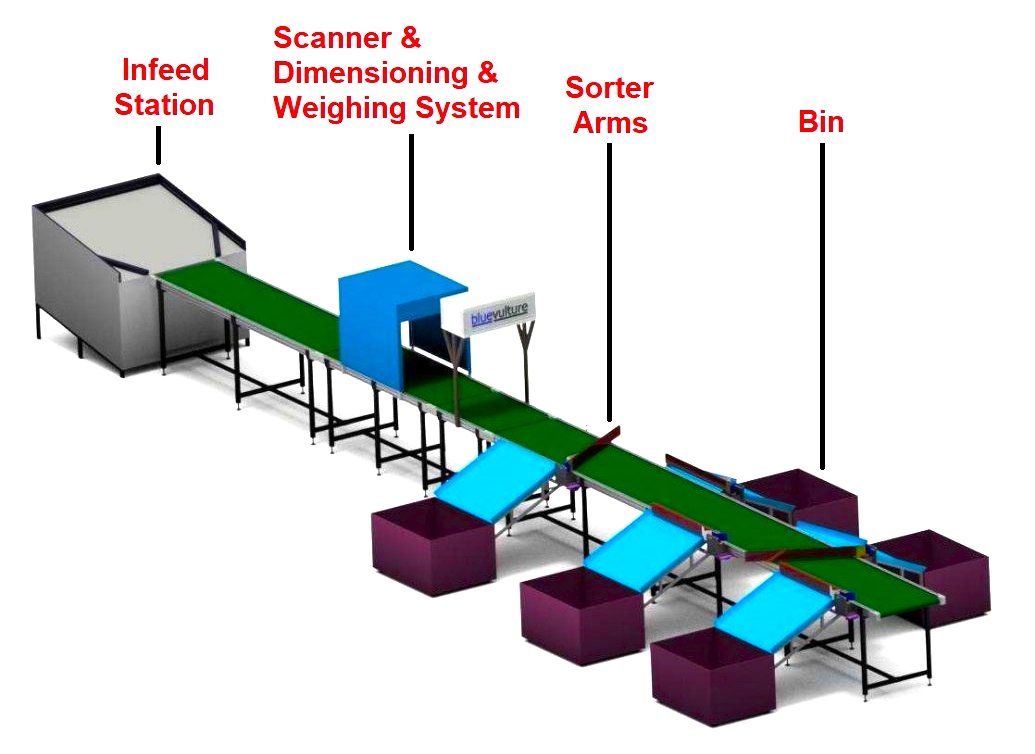
We have a conveyor system that is supposed to identify incoming products and sort these products along the way between 5 different Bins.
We have 5 destinations for our products and we have 20 different product types. The products are sorted as follows:
| Product Type | 1, 2 and 3 | 4 to 9 | 10 to 13 | 14 and 15 | 16 to 20 |
| Destination Bin | Bin 1 | Bin 2 | Bin 3 | Bin 4 | Bin 5 |
To identify products, we have a scanner system that detects a product and gives it an identification number from 1 to 20.
To simulate our products, we will create a PLC function that will give us a random number from 1 to 20
And to guide the products to their Bins we have 5 pneumatic arms that extend and retract to guide the products.
The product takes about 15 seconds to move from the Scanning station to the end of the line.
| Destination | Bin 1 | Bin 2 | Bin 3 | Bin 4 | Bin 5 | End of line |
| Time to reach | 2 Sec | 4 Sec | 6 Sec | 8 Sec | 10 Sec | 15 Sec |
PLC Sorting Conveyor System Logic
- We have a simulation function for the products, this FB gives us a random number each 1 sec to simulate the presence of a new product on the conveyer each 1 sec.
- Once there is a new product, the system will compare the number it has to know which bit this product will activate in the shift register.
- After a certain bit is activated, for example, %M50.0 for products 1, 2, or 3- this bit will be set to 1 and with the help of the index signal and SHL instruction, this bit will be shifted to the left each 500ms.
- We know how long it takes to reach each bin, and we know the index signal frequency – 2Hz-, so we know at which bit of the register the product will be in the right place. And then we can activate the Arm to push the product to the Bin.
- See the next Pictures for more clear idea.
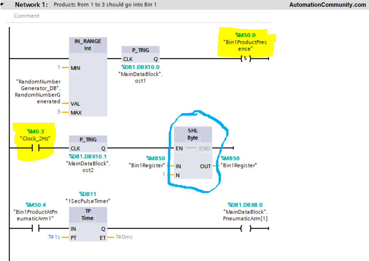
Products 1, 2, and 3 should go to Bin1 (as per above image)
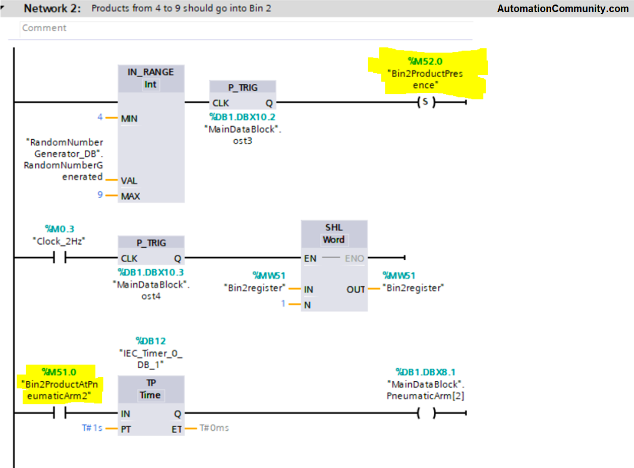
Products from 4 to 9 will go to Bin 2 (as per above image)
Can you see which BIT does this group of product activate?
Can you see which Bit will activate the arm?
The same concept is done for the rest of the products.
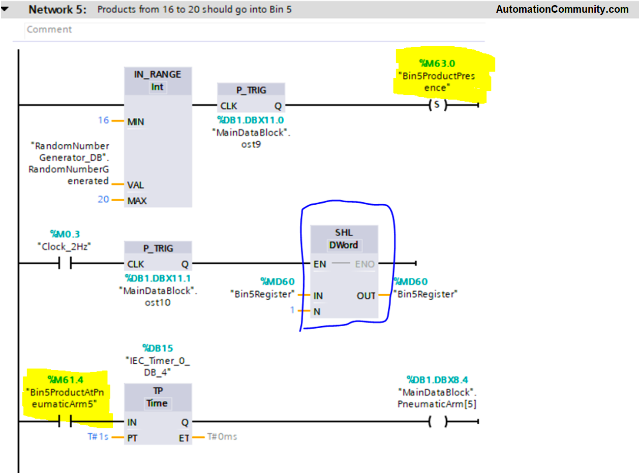
See the next picture for products from 16 to 20 (below image)
The next video will show a simple Visualization of the shift register code we just made.
Can you notice the BIT at which the arm is activated for each product?
You can download the PLC source code and try the simulation yourself using Siemens Tia Portal.
If you don’t have Siemens PLC software, then download the PDF of the sorting conveyor machine logic.
Conclusion
Shift Register is very useful and commonly used in a lot of industrial processes. Especially when you want to monitor the case of a certain event along a moving process, so that when this event arrives at the point where we need to take action the process will know what to do with it.
This article was published in the Automation Community Competition.