In this article, we will Learn what is a Safety PLC with an example program of an emergency pushbutton in a safety PLC and their advantages & disadvantages.
To better understand Safety PLCs, why we need them, what advantages they provide, and how to use them, we need first to explain some basic information about machine safety and safety control circuits.
In the end, we will give a practical example of how to use a safety PLC (S7-1500 & TIA Portal) to program two of the most common safety control circuits, the Emergency Push Button and the Safety Door interlock.
What is Machine Safety?
Workers’ safety in industrial processes has always been a very important aspect of any machine and with the very fast revolution of industrial processes and machinery, safety standards like OSHA in the US and EC directives in the EU have put strict rules for safety requirements for industrial processes and production machines, to ensure workers safety inside a production plant.
Yes, automation has invaded industrial processes, but never the less, the presence of operators and workers is still very critical for the well-being and well-performance of the process, and hence, the importance of safety regulation for today’s production sites.
The basic concept of workers’ safety in industrial processes can simply be put under two points:
- Keep workers away, while the machine is running:
This can be achieved with safety gates to keep workers in a safe space, and presence detection to figure out if someone is in a risk area. Many other safety components like ( interlocking devices, two-hand controllers, and enabling switches) can be used to provide safety information that can be used to take a decision of stopping the machine or not allowing it to start from the beginning unless all safety regulations are met.
- Stop the machine in a safe manner, if a risk condition is presented:
Again, safety components can provide information that will be deciding factors whether to allow the machine to run or not. And also integrates safety diagnosis elements that can detect the failure of a certain safety condition, to trigger a safety action (either to stop the machine or keep it from running).
Risk Assessment of Industrial Processes
Assessing whether your process will pose any safety risk to your workers is the first step to execute when designing safety measures for your machine. The objective of risk assessment is to define which Risk Category your process falls under
Risk assessment can be done through the following 5 steps:
- STEP 1: Determine the limits of your process.
This includes defining the intended use of your machine and the operation required for the process.
- STEP 2: Identify the Hazards.
This includes defining areas of hazards for workers, like moving parts and surfaces with high temperatures
- STEP 3: Estimate the Risk associated with these hazards.
After identifying hazards associated with your process, the Risk is estimated from the possibility of this hazard occurring and the level of harm.
- STEP 4: Evaluate the Risks.
In this step, the hazard level of your process is defined. After you estimate the risks, you need to evaluate these risks to determine if the risk level must be reduced. If yes, then safety measures must be taken.
- STEP 5: Take measures to reduce the Risk.
After you have defined the hazard level of your process, proper safety control circuits should be designed to reduce this safety risk.
Hazard Levels and Safety Circuits Categories
Risk assessment is used to determine the hazard level of your process and what kind of danger it has to your workers. Risk levels are classified into five different levels and they are B, 1, 2, 3, and 4 where level 4 is the most dangerous level.
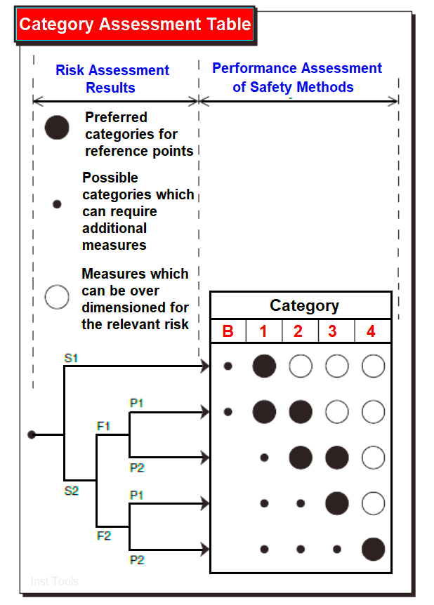
ISO 13849-1: 1999 classifies the hazard levels of a machine by defining 3 factors as follows:
- S: what is the Severity of the injury
- S1: Slight injury.
- S2: Severe injury or death.
- F: frequency and/or exposure time to the hazard
- F1: Happens rarely or for a short time.
- F2: Happens often or for a long time.
- P: the possibility of avoiding the hazard
- P1: Hazard can be avoided.
- P2: Hazard is inevitable.
See the following picture for the classification of the dangerous levels of a machine.
What is a Safety Condition? How to Detect it?
A safety condition is a state that can pose risk to an operator or a worker in the production site if the process continues to run or if the process was allowed to run.
Safety conditions can be detected in 2 ways:
The machine itself can detect the safety condition
By the use of safety components and safety circuits, a machine can detect a risk condition like the presence of an operator in the moving space of a robotic arm.
Internal diagnostics of safety components provide a higher level of safety, as they can detect the internal failure of components that might cause safety risks if not working properly.
An operator detecting the safety condition
Industrial automation gives the operator a way of acting when observing a safety condition, through the existence of emergency push Buttons which will trigger a safe condition for the process and ensure stopping the machine in a safe manner, as fast as possible.
What is a Safety Control Circuit?
Also called a safety-related control system or SRCS, it is the safety logic embedded into your machine to ensure that a hazardous condition will not occur during machine running or to prevent the process from running until all safety conditions are met. The safety control circuit can either be a separate system from your process logic or it can be implemented with the normal logic of machine operation.
The safety control circuit can be as simple as a guard interlock limit switch connected in series with the control logic of a power contactor, or it can be a complicated safety PLC communicating with multiple safety relays and interlocks.
The level of complexity of a safety circuit depends mainly on the hazard level of your process as your process hazardous level increases from B, 1, to 4 the associated safety circuit needs to be more efficient in handling the risks of your machine and provide a more stable and safe environment for all workers.
As we have five hazard levels for machines, we also have five performance levels of a safety circuit, and they have the same naming B, 1, 2, 3, and 4.
The level of competence and efficiency of a safety circuit depends on two main and very important points.
How many safety precautions are being implemented?
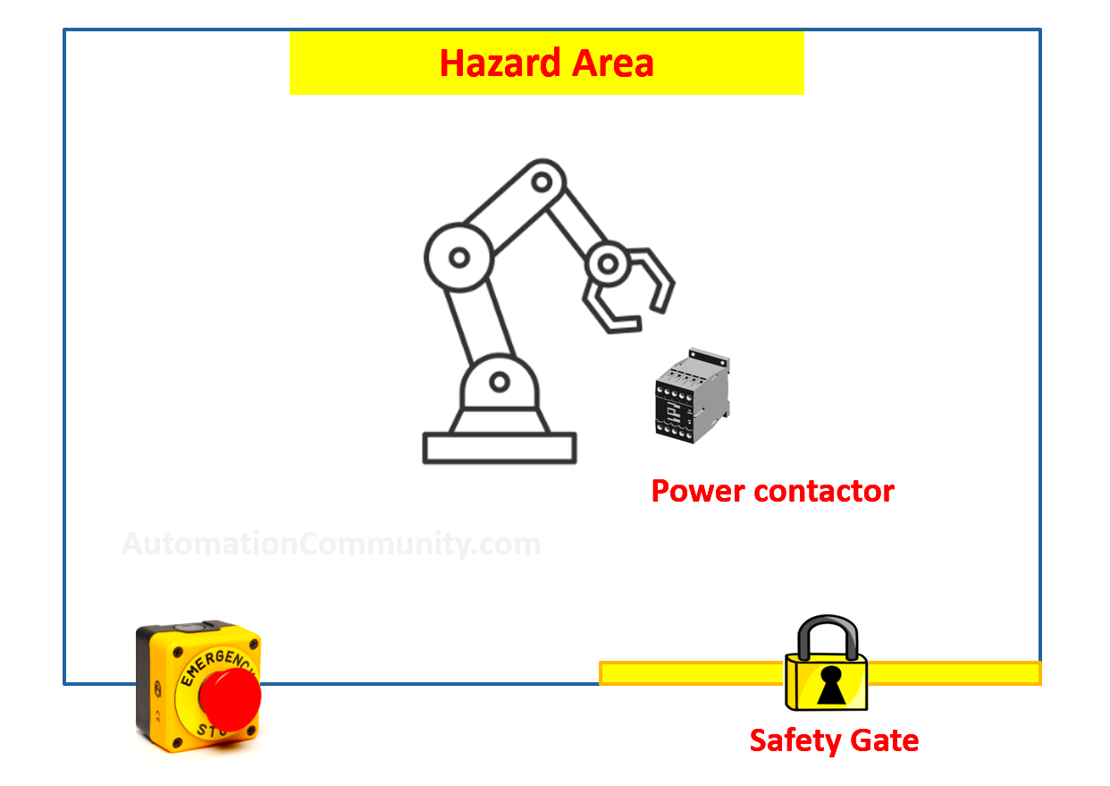
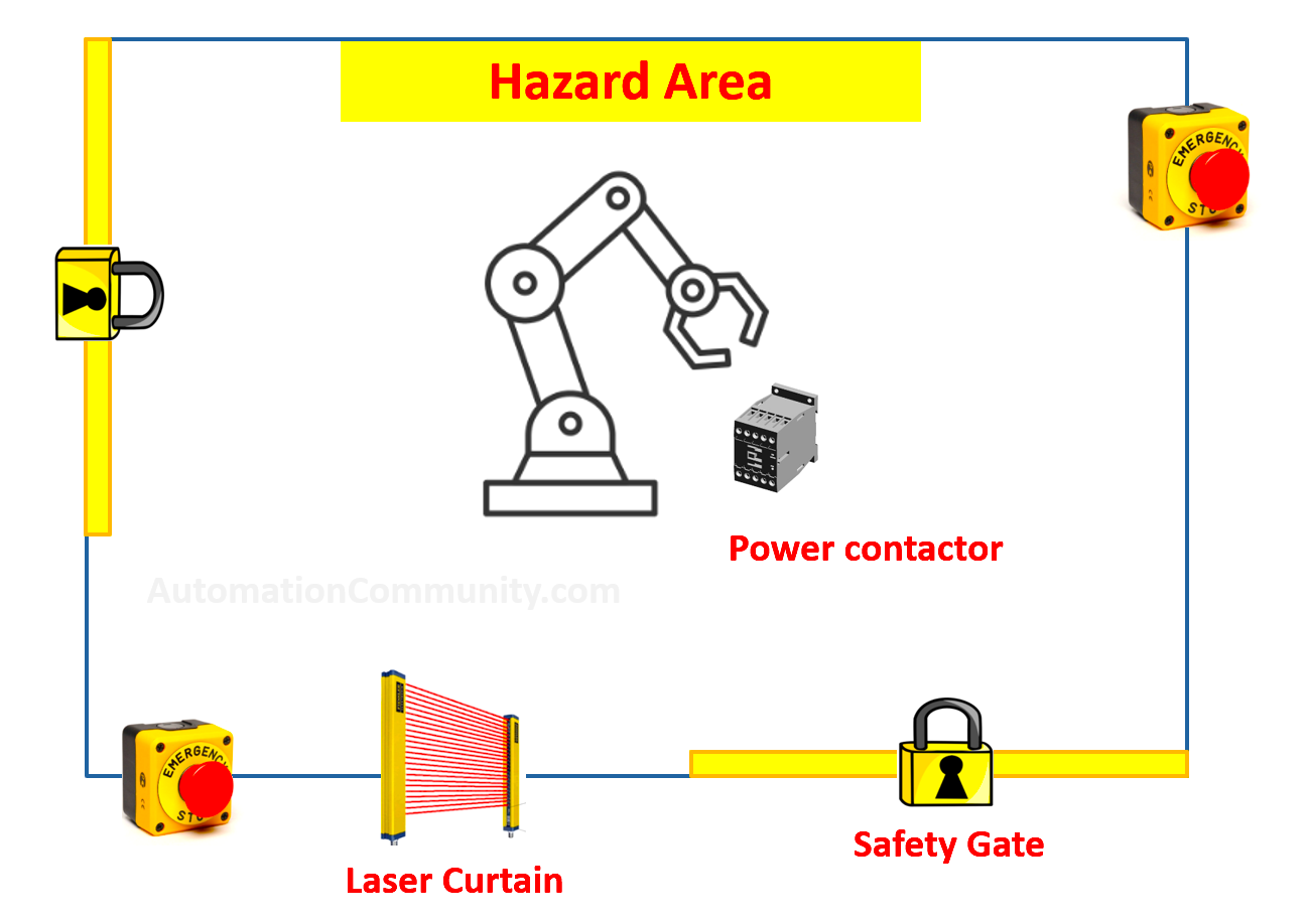
Is the risk area being monitored with only a safety door switch, or does it has a more complicated system including laser curtains and press sensors for all space inside the hazard area? See pictures 2 & 3
What about internal failures?
Can the safety circuit detect internal failures of safety components? Will it be able to continue to operate the safety function correctly even after internal failure is detected?
These two points are also the judging factors to which performance level the safety circuit belongs.
In order to provide a competent and efficient safety circuit, the safety functions must continue to operate correctly even if a failure condition occurred in the safety circuit.
Examples of these failures include:
- The emergency push button contacts are welded together.
- An internal failure inside a safety device.
- An attempt from a worker or an operator to bypass safety conditions.
- The power contactor contacts are welded together
What is the Safety Function?
The safety function of any safety control circuit is simply being able to stop your process or prevent it from running if a hazardous condition has occurred.
Your system should be able to detect a risk condition occurring and take adequate actions to prevent this risk. The optimum goal is to keep the safety function alive even if a failure has occurred in your safety control circuit.
Safety Control Circuits Categories
The following table.1 shows a summary of the principles for the design of safety-related parts of control systems as per The European Standard EN 954-1.
| Category | System Requirements | System Behavior |
| B | Safety-related parts of machine control systems and/or their protective equipment must comply in accordance with relevant standards so that they can withstand the expected influence. | Internal failures of safety components can’t be detected. If an internal fault occurred, the safety function will be lost. |
| 1 | The requirements of category B applySelecting more reliable safety components, to reduce the likelihood of internal failures. | Internal failures of safety components can’t be detected If an internal fault occurred, the safety function will be lost. |
| 2 | The requirements of categories B and 1 apply. The health of the safety function is checked at the startup of the system and periodically, | The loss of a safety function can be detected by the check. If a fault is detected at the check, a safe state shall be initiated or a warning shall be given. If a fault occurred between checks, the safety function can be lost. |
| 3 | The requirements of categories B and 1 apply. The system is designed so that a single fault in any of its parts does not lead to the loss of a safety function. | The system can detect some faults, but not all faults will be detected. The safety function is not lost, if only a single fault occurred. An accumulation of undetected faults can lead to the loss of safety function |
| 4 | The requirements of categories B and 1 apply. The system is designed so that a single fault in any of its parts does not lead to the loss of a safety function. Accumulation of faults should not lead to a loss of safety function. | The system can detect all faults. The safety function is always performed, even if faults occurred. |
Table 1 – Summary of principles for the design of safety-related parts of control systems as per The European Standard EN 954-1.
Now that you know basic definitions of terms like safety control circuit, safety function, and performance levels of the safety circuit. And after reading and hopefully understanding the previous table, go back to pictures 2 & 3 and see if you can classify which circuit is category 1 and which is category 4.
If you think that the safety circuit in picture 2 belongs to category 1 and the safety circuit in picture 3 belongs to category 4, unfortunately, that is not right.
If you think that the safety circuit in picture 3 belongs to category 1 and the safety circuit in picture 2 belongs to category 4, unfortunately, that is also not right.
The right answer is that both safety circuits in Picture 2&3 can belong to category 1 and also can belong to category 2, 3, and 4.
We never said that more safety components in your circuit will mean a higher safety category. The concept is very simple:
- Can you detect a failure in the system or not?
- Can you keep the safety function alive even if a failure has occurred or not?
Those two points are the judge of what category level a safety circuit will belong to. And not how many safety components are being used.
Explaining the 4 Safety Control Circuit Categories
The following pictures will show how a simple safety circuit containing just an interlock switch and a power contactor can belong to the 4 safety categories.
Category 1 – Safety Circuit without Failure Detection
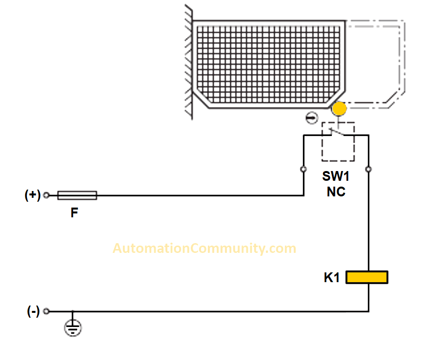
The safety circuit in picture 4 belongs to category 1 because the system can’t detect if a failure occurred in the SW1 or the K1. And so if a failure happens, the safety function will be lost.
Category 2 – Safety Circuit with One-time Failure Detection in One Component
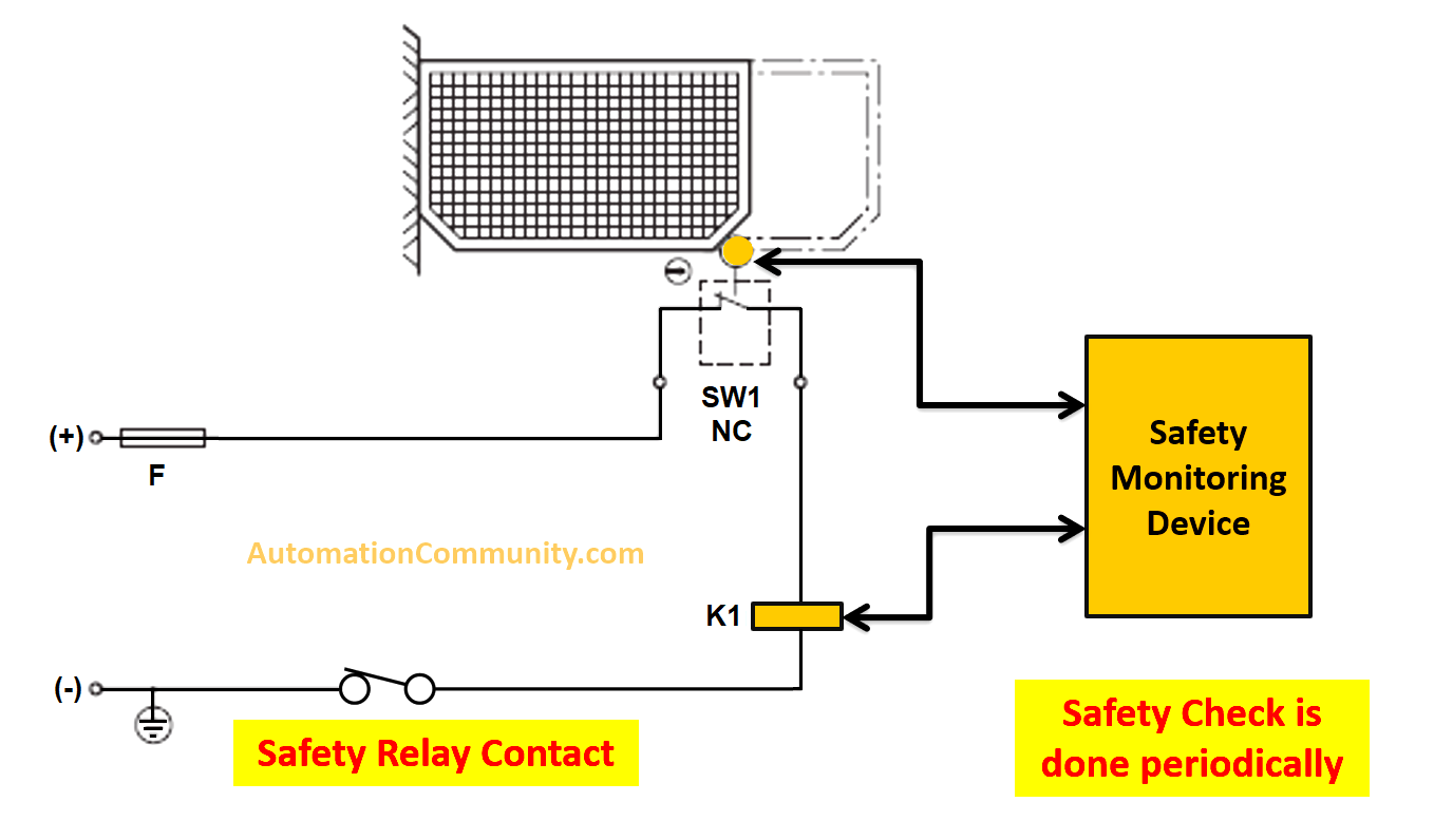
The safety circuit in picture 5 belongs to category 2 because now you can detect if a failure occurred in one of the safety components, but only at periodic checks.
If a failure is detected at the safety check then the safety relay contact will open to prevent the machine from running, but if a failure occurred between safety checks, the safety function will be lost until the next safety check.
Category 3 – Safety Circuit with Redundancy
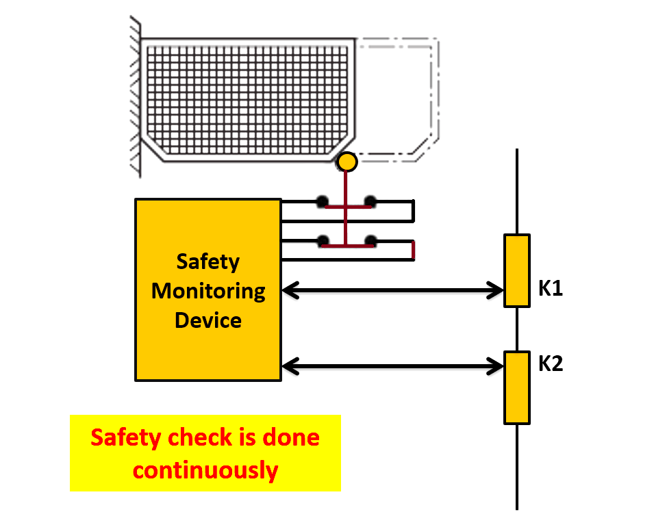
The redundancy provided for the inputs (dual channel interlock) and redundancy in the output (contactors K1&K2), plus the continuous check for internal failure of components make the safety circuit in picture 6 belong to category 3.
If only a single failure occurred, for example in K1, the safety function will not be lost. But if an accumulation of failures occurred, for example, failure in K1 and K2, the safety function will be lost. Also in category 3, some failures can’t be detected, so an accumulation of undetected failures can lead also to loss of safety function.
Category 4 – Safety PLC with Diagnosis & Redundancy
For the safety control circuit to become category 4 the accumulation of failures should not cause the safety function to be lost, this is usually achieved by ensuring high-frequency monitoring techniques.
For the sake of redundancy and better diagnosis coverage, the safety monitoring device in categories 3 and 4 are usually safety PLCs. See picture 7.
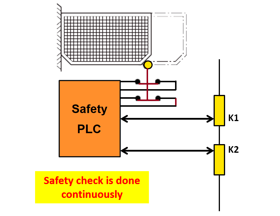
As we said before, the safety circuit in category 4 will be designed so that an accumulation of failures will not lead to the loss of safety function.
The Need for a better Machine-Stopping Sequence
All previous safety systems mentioned before included hard-wired safety contacts of the safety device to the power contactor of the part of the machine that needs to be monitored against hazards.
But industrial processes these days are controlled using one control device, it will very likely be a PLC, now imagine if a safety condition was triggered in a part of the machine and the safety device stopped this part of the machine, if a part of the process was shut down by any means other than the main process controller (the PLC), this could lead to severe machine damage.
And also a lot of problems can be met upon restarting the machine because the PLC might not know the actual process state at the moment.
So the safety control circuit should also take into consideration not just stopping the process, but also stopping it in a safe manner. And that is another reason for using safety PLCs.
What is a Safety PLC?
A safety PLC is a standard PLC in the sense of being able to control industrial machines, but it also has integrated safety functions that allow it to control safety control circuits as well.
Safety PLCs are designed to force the process to a known state before safely shutting down the machine when a safety condition is triggered by for example a triggered emergency push button.
Safety PLCs have amazing diagnosis capabilities; they are able to monitor field devices against internal failures such as broken wires or shorted contacts.
Safety PLCs are designed to be very robust against software and hardware internal failures.
Advantages of Safety PLC
- Safety PLCs are designed, tested, and certified to comply with safety standards.
- Great diagnosis, monitoring, and redundancy of input and output signals.
- Self-diagnosis of internal software and hardware.
- Very robust and very hard to fail.
- Separate software for safety functions.
Disadvantages of Safety PLC
- The initial cost is very high.
- Require skilled and highly trained personnel for installation and maintenance.
- Software programming can be very complex for some applications.
Operation of Safety PLCs
When using a safety PLC, you get two separate programs inside the PLC, one code for the normal operation of your process, and the other code dedicated only to the safety functions.
The two codes are being executed together at the same time, but the safety code will be executed many times in one execution of the normal PLC code, see next picture 8.
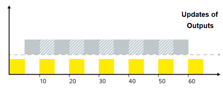
Every yellow block represents one execution of the safety program. The basic concept is that the safety program and standard program are running in parallel with each other. Every once in a while the safety program will interrupt the standard program, evaluate all safety-related functions, and then give that information back to the standard program.
As you can see from picture 8, the safety program was executed 6 times within 1 scan of the normal program.
It should also be mentioned that you could have the same behavior with a normal PLC by using cyclic interrupt routines. But as we mentioned before the safety PLCs are very robust against both software and hardware failures, they are specially designed to keep the safety function alive, no matter the condition. Whereas the standard PLC is prone to internal failures and software crashes, so a safety PLC will be the better choice.
Emergency Pushbutton Safety PLC Example Program
Now, we will give an example of how to configure a safety PLC and program an emergency push button in the SIEMENS TIA Portal.
Open your TIA Portal software and create a new project and add a safety PLC, in our example we used the 1515 TF-2 PN PLC. See picture 9.
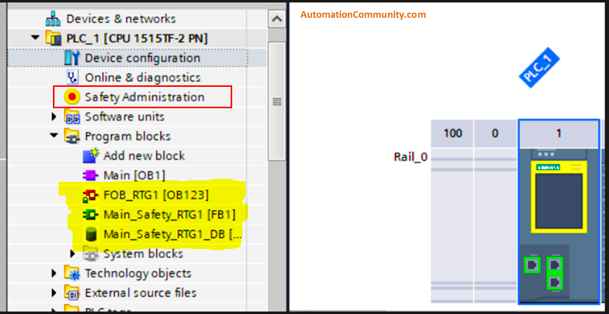
The highlighted blocks are already created when choosing a safety PLC, as we said before it is designed and standardized for safety applications. The OB123 is the yellow block you saw in picture 8. Once the PLC is in run mode, it will continuously call and execute the safety functions inside the highlighted blocks.
If you open the properties of the CPU, or if you clicked the safety administration icon on the left. You will find a lot of safety-related parameters you can set and/or change. See pictures 10 and 11.
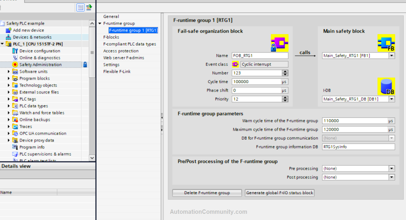
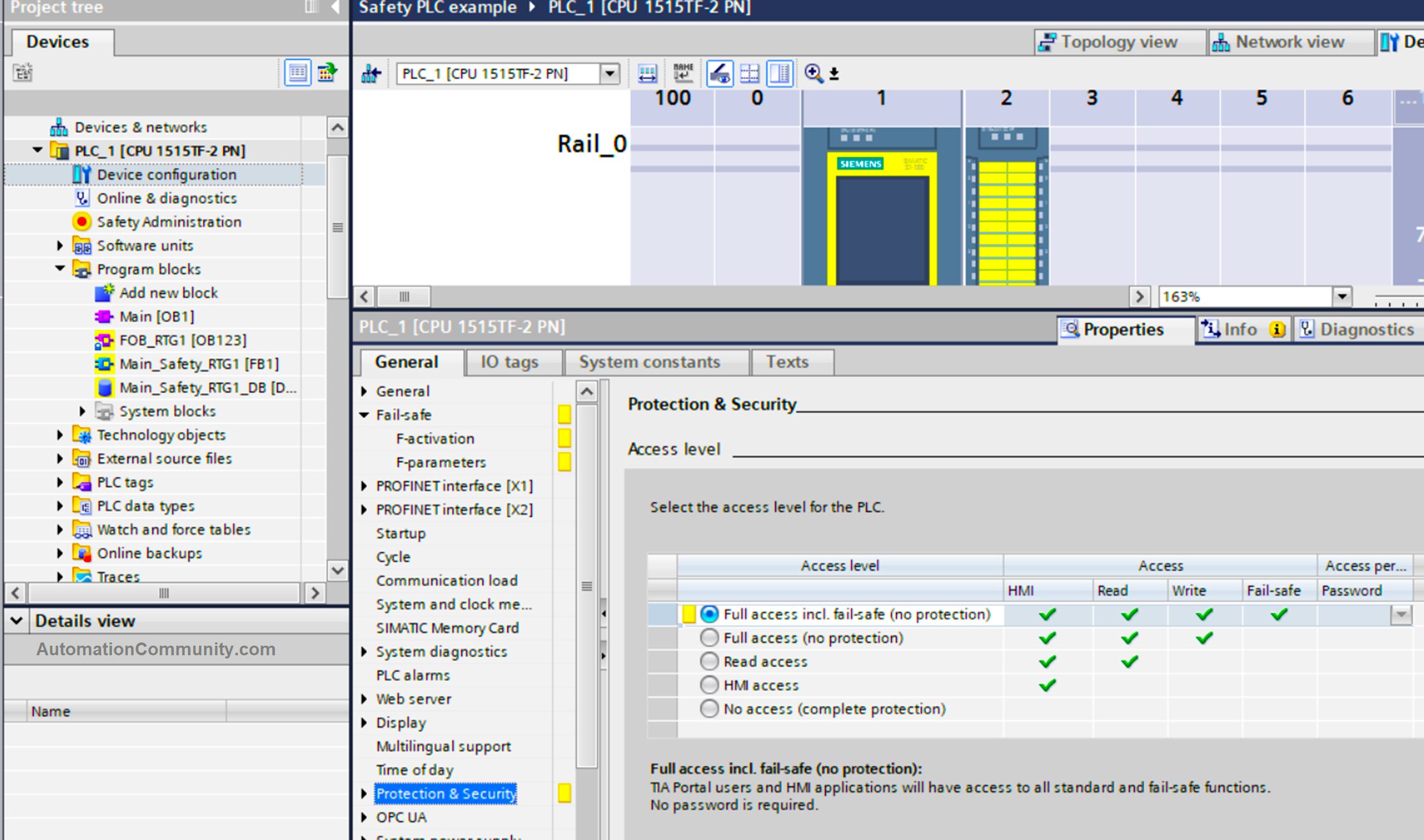
As you can see, there are a lot of safety parameters. That you can change.
Safety modules have many internal parameters and many internal functions for monitoring and other safety-related things. You usually don’t need to touch them because they are already set in a way that is complying with safety standards, you need to have the needed knowledge and experience if you want to manually set one of these parameters.
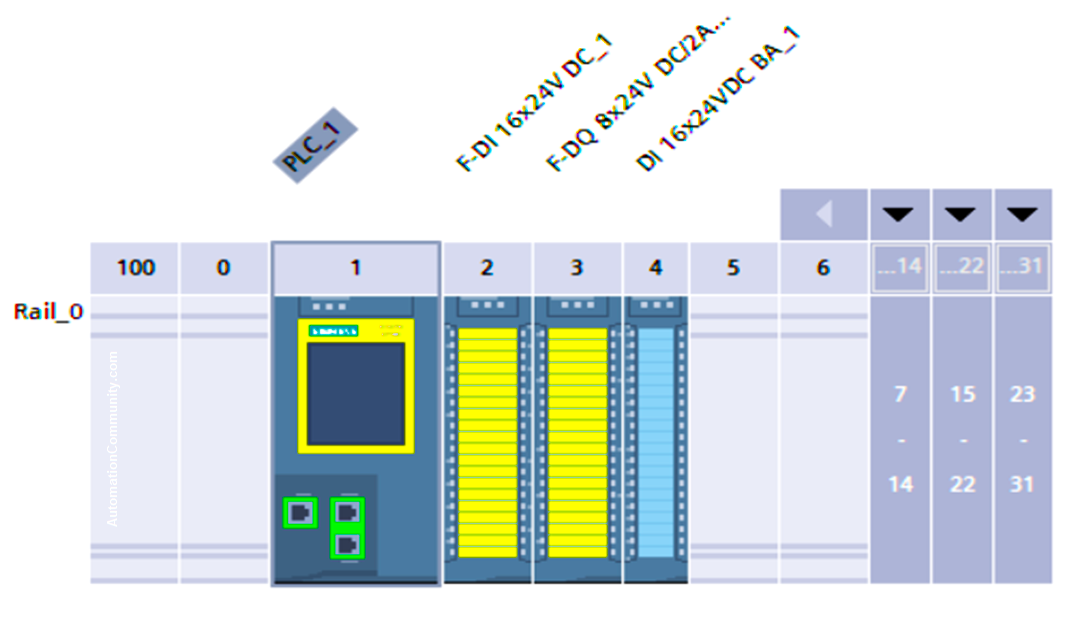
Next, we will add a safety digital input module, a safety digital output module, and a standard digital input module. As you see in picture 12.
Now, we set the tags of inputs and outputs.
- E-Stop: %I0.0 taken from safety input module.
- Motor: %Q9.0 taken from safety output module.
- ACK: %I15.0 taken from standard input module.
For the sake of redundancy, you should expect that the emergency push button will have dual channel contacts, and for the same reason, the input channels in the safety module always come in pairs, as you can see in picture 13.
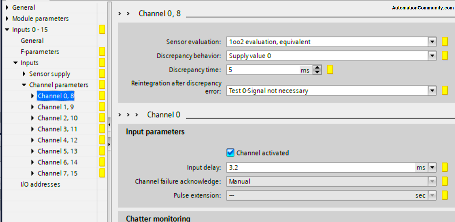
As you can see, channels 0 and 8 are paired together, so when we set a tag %I0.0 for E-Stop.
That means we will connect the hard-wired contacts of the emergency push button to %I0.0 and %I1.0 of the module. As shown in picture 14.
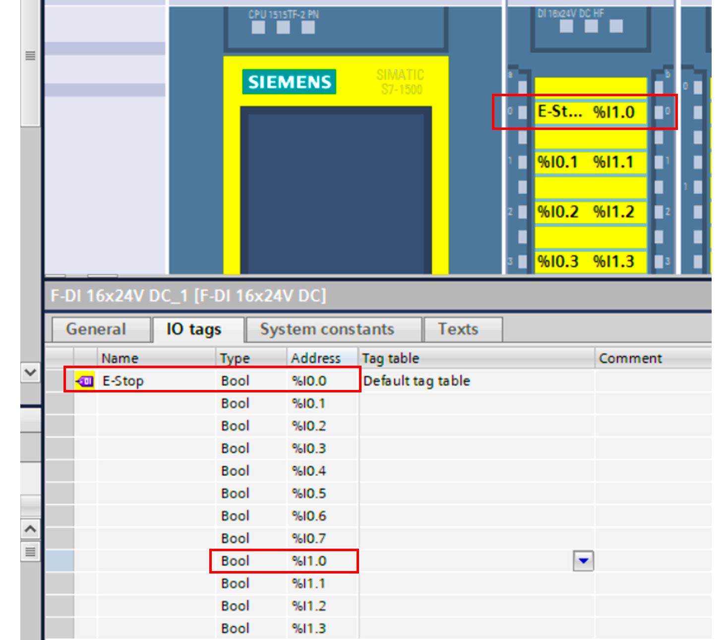
So, in the software, I only use the lower channel for programming, but I connect both channels as hardware.
The next step is to start programming.
Open Main_Safety_RTG1 [FB1]function block, and then open the safety functions in the instructions tab.
You have special instructions for your safety blocks; they are standardized and guaranteed to ensure safety.
For example, emergency stops two hand enabling, safety doors and more See picture 15.
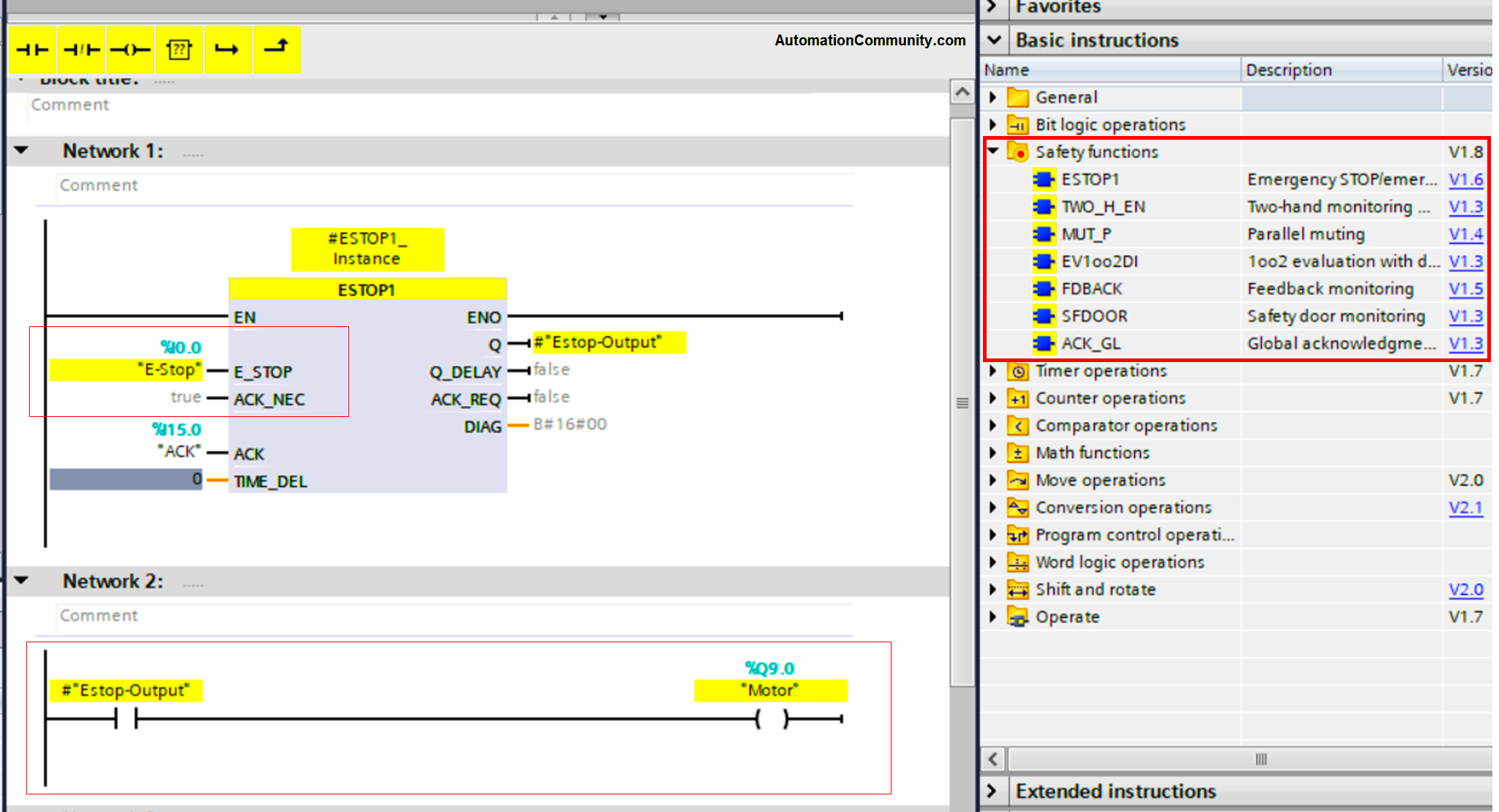
For our example, we will select the ESTOP1 for emergency stop circuits.
As you see from the picture the block is colored yellow indicating safety functions are being configured inside. Set the %I0.0 to the E-STOP input bit of the block and create a static tag
“Estop-Output” as the output of the Block,
Use this output to trigger the Motor.
Compile your PLC logic, start a new simulation, go online, and start experimenting with the inputs and see how a safety emergency setup will work in the simulation.
For some notes, you should know, see picture 16.
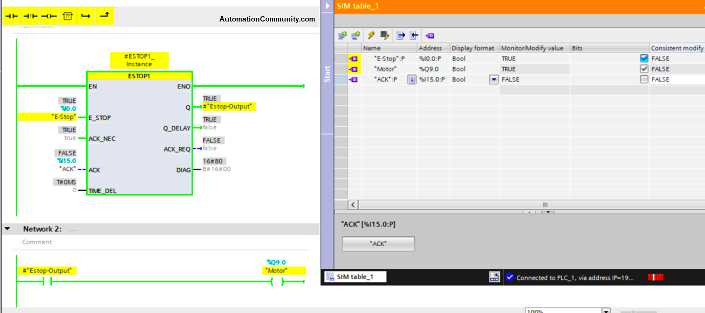
At the start, when there is no emergency active, the output will be ON. Now, see picture 17.
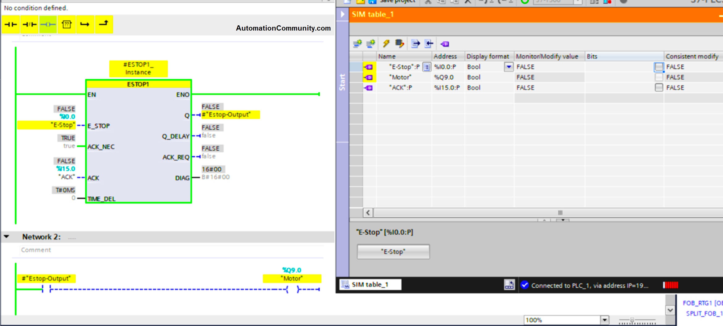
When the emergency is triggered, the output is immediately OFF.
Picture 18 will show what will happen when the emergency condition is cleared.
Did you notice that the output was still OFF, even when the emergency condition was cleared and the system was back to normal?
For an emergency push button function, you should know that whenever an emergency event is triggered, after resetting the emergency to a normal case, you need to acknowledge the emergency before you can have an output again.
We here mean the output of the emergency function, not the Motor, we have connected this output directly to the motor for the easier explanation, but you should know that your standard programming should not allow the motor to run directly after acknowledging the emergency and that it should wait for another start signal from the operator.
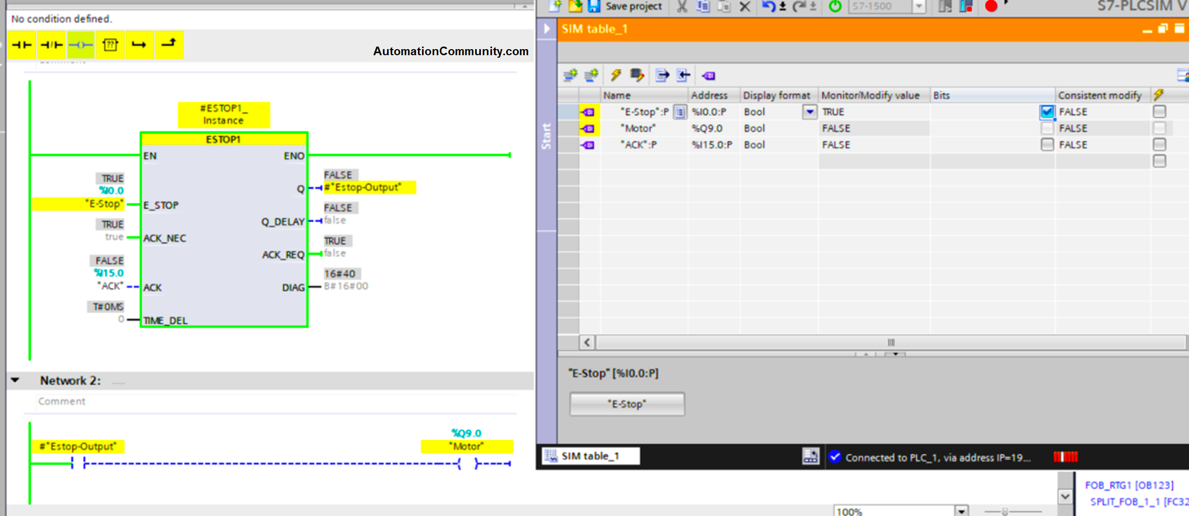
So if there is an emergency and the output (Estop-Output) is cut off, the output will not go back on until you acknowledge. And that is why the ACK input was made. See what happens after we press ACK. In picture 19.
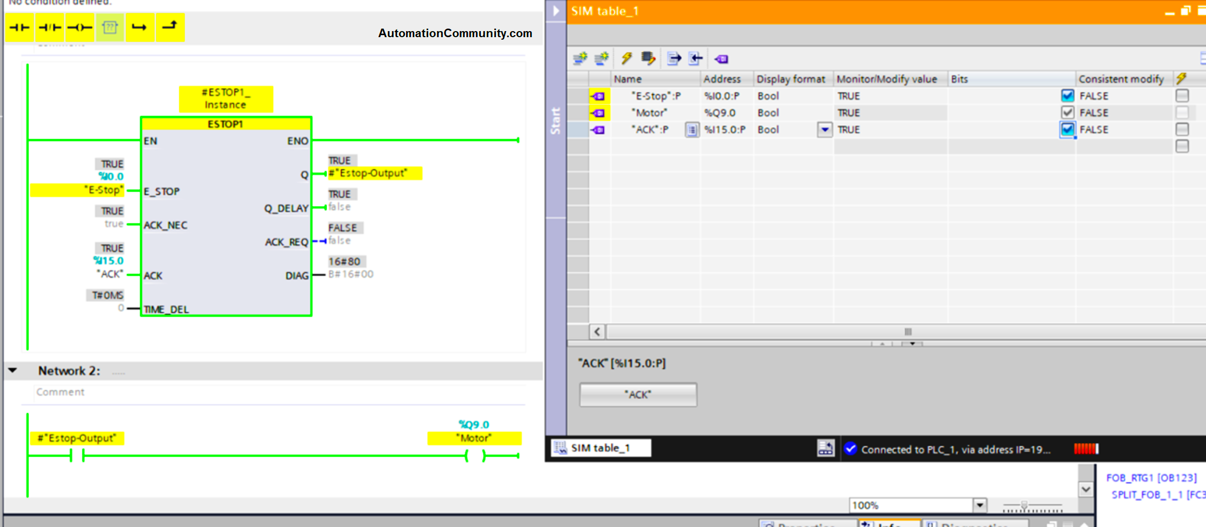
Now, after we acknowledged the clearance of the emergency, the output was back ON.
Again, there should be another enable signal for restarting the output to come from the operator, because we don’t want to start the motor by itself after the acknowledgment.
This was a simple code for setting an emergency function with a safety PLC, you noticed that we have not done much, because as we said before, the safety PLCs are standardized and preconfigured for safety operations.
P.S.: Password protection of the safety PLC inside the provided code is set to 123
Download this Safety PLC code in PDF format and the Safety PLC TiaPortal program.
Conclusion
Safety is a very critical part of any industrial process; strict standards have been developed to ensure the safety of workers and processes. With the continuous demand from automation processes and demand for more reliable safety measures, safety PLCs are becoming very critical elements of industrial machines, providing that level of high safety requirements.
Read Next: