In this article, you will learn the PLC programming for clay brick making machine and its basic steps of operation.
Clay Brick Making Machine
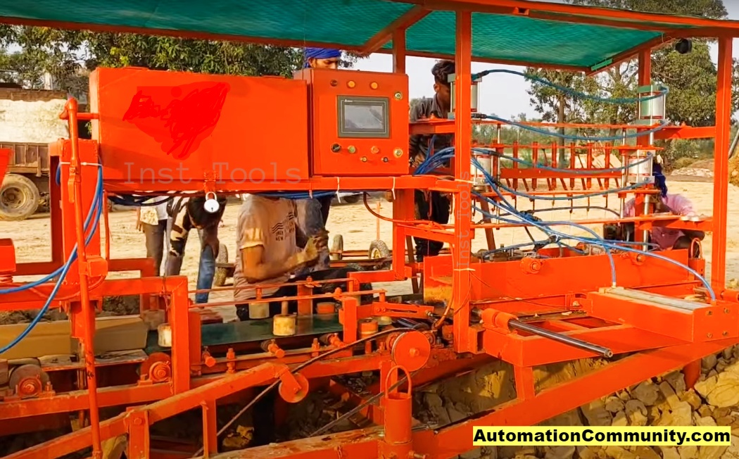
The clay is cut into one enormous rectangular cuboid piece using the machine below after it has been extruded and trimmed to a precise dimension.
This portion is further divided into ten printed bricks of the same size.
Delta PLC (DVP 14SS2) and Delta HMI (DOP107CV) are used in this machine.
I/O List
The list of IOs with information about the timers used in the PLC program is provided below.
- X0 – Proximity Sensor Input
- X1 – Photo Sensor Input
- X2 – Start button
- X3 – Stop button
- Y0 – Clay Pressing Valve
- Y1 – Clay Slicing Valve
- Y2 – Clay Side Pressing Valve
- Y3 – Printing Valve
- Y4 – Clay Pushing Valve
- Y5 – Conveyor Valve
Brief Process Explanation
Conveyor rolls on to transfer the portion of the extruded clay that has been cut off to the place where it will be printed with alphabets or words while being pressed vertically and horizontally.
It is then pulled from the machine. It is subsequently divided into ten equal parts throughout the dragging process.
PLC Programming for Clay Brick-Making Machine
The PLC ladder logic for the brick-making machine is as follows.
Rung 1 & 2
Unless M20 actuates to switch on the system when Start Button X2 is pressed in Rung 1, all the Valves and memory bits are reset in Rung 2.
Rung 3
ALT is used to set and reset the M0 bit alternately when Clay Sensing Sensor gives a pulse of X1 each time. This only happens if all the valves and memory bit M1 are deactivated and X0 is continuously high.
When the Clay Pushing Cylinder is in the Reverse state or the Clay Pushing Valve is not engaged, the proximity sensor’s feedback input, X0, is always detected.
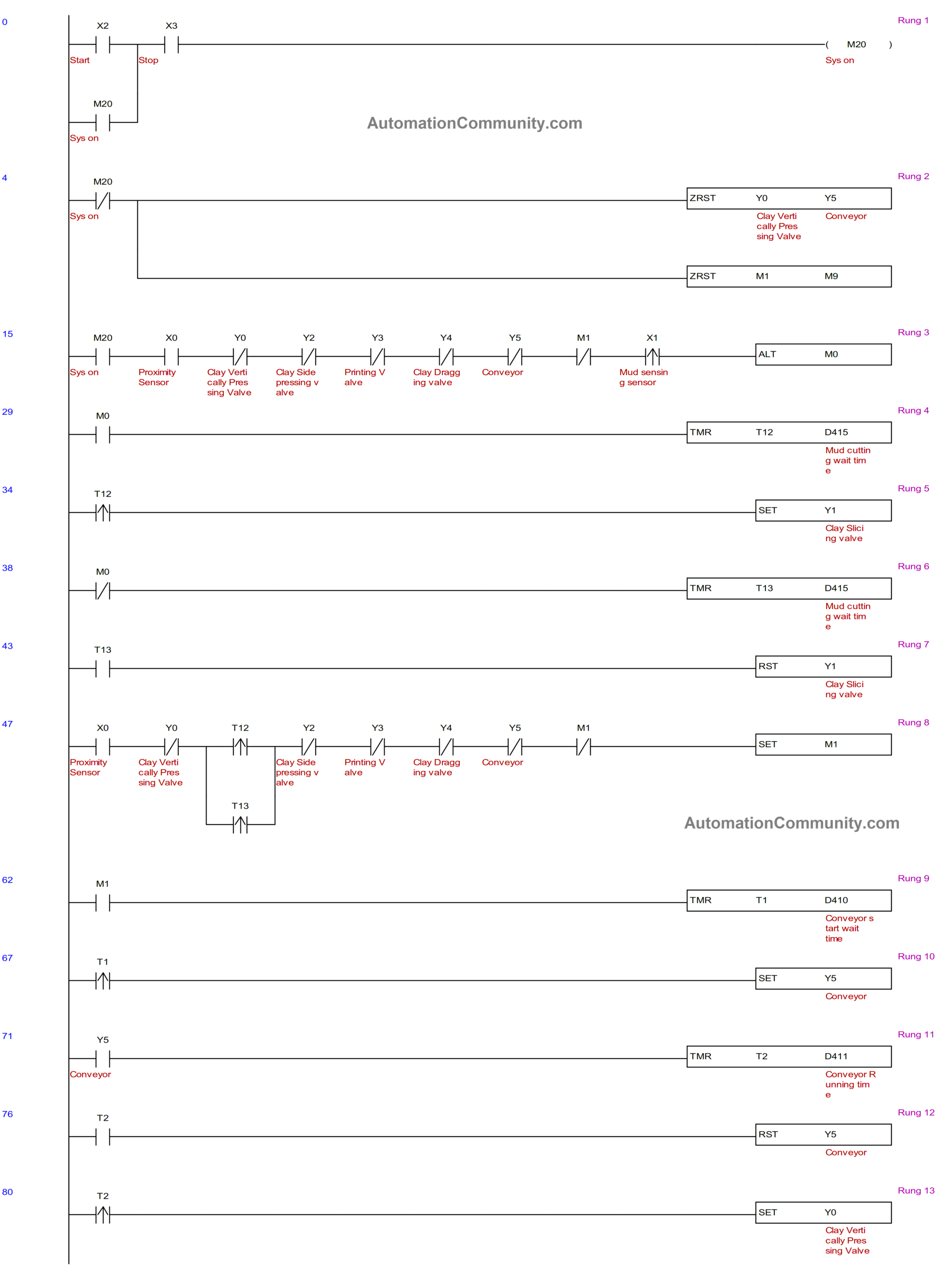
Rung 4, 5, 6, & 7
Using Slitting Rope that is mechanically attached to the cylinder, clay is cut. When Y1 is set and reset in succeeding cycles, this rope alternately slices the Clay from below and upward. (See Video)
Timer T12 begins keeping track of the Pre-set time specified in D415 from the HMI when M0 is set in Rung 3 for the first cycle. As soon as this period of time is through, Y1 is set to slice the Clay in a downward direction.
Y1 is made set for the duration of the cycle and won’t reset at its conclusion. When the second cycle begins and Clay is once more detected by X1, M0 is reset, causing the timer T13 to start counting at the same moment.
When the timer runs out, Y1 is reset to cut the clay in an upward direction.
This process goes on subsequently.
Rung 8
M1 is set from the done bit pulse of timer T12 for odd cycles, whereas M1 is set from the done bit pulse of timer T13 for even cycles.
Rung 9 & 10
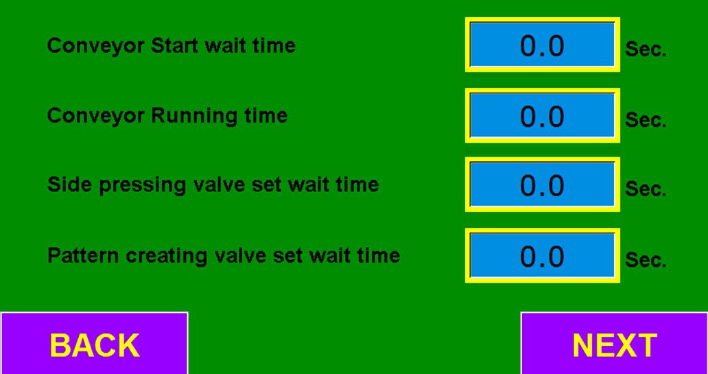
The conveyor then rolls to move that piece of sliced clay into the area for printing and more clay slicing. This only happens when M1 is enabled, causing Y5 to set after the predetermined period in D410 of timer T1 has passed.
Rung 11 & 12
Just when the designated time in D411 of timer T2 has expired, Y5 is reset, forcing the conveyor to stop rolling.
Rung 13, 14, & 15
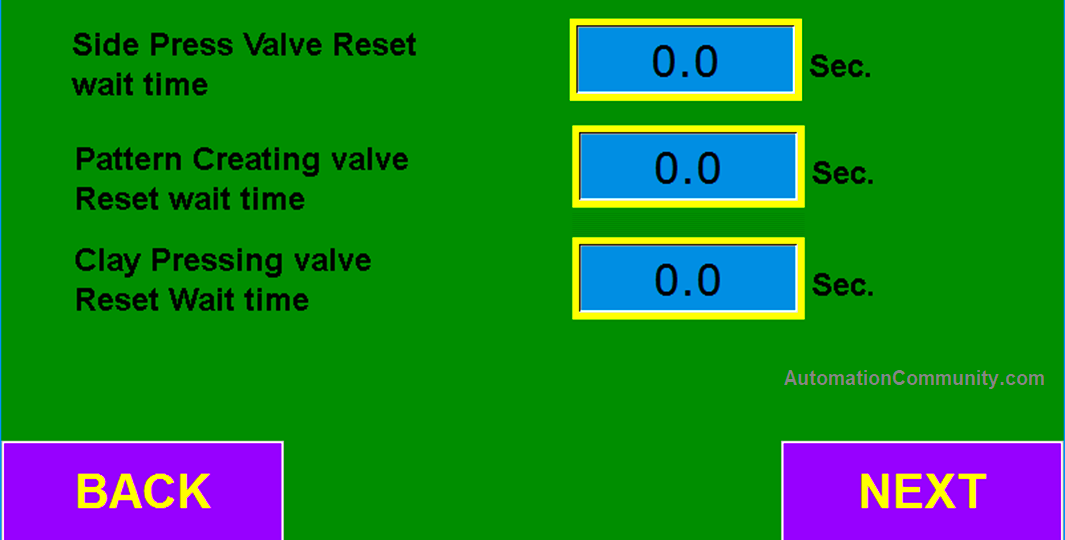
Y0 is triggered, causing the cylinder to press and hold the sliced clay from an upward direction just as the conveyor rolling comes to an end. Once the predetermined time in D412 of timer T3 has passed, it is then pressed from the sides through the actuation of Y2.
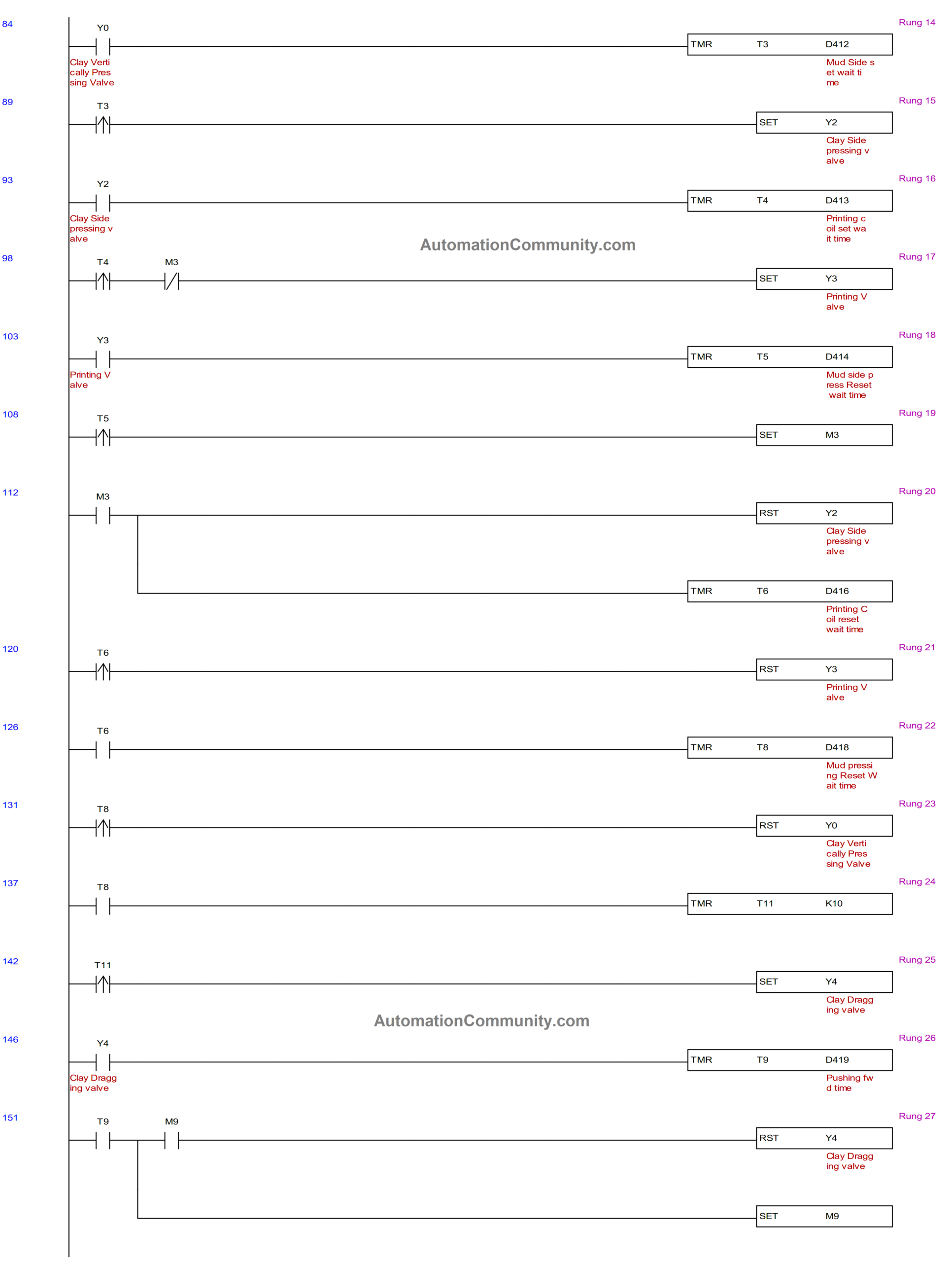
Rung 16 & 17
The wet Clay is now held in place in order to create patterns in the shape of letters using a stamp mould attached to a pneumatic cylinder, whose valve opens when Y3 is set after the predetermined time in D413 of timer T4 passes.
Rung 18, 19, & 20
As soon as Y3 is set, timer T5 begins to build up its pre-determined amount of time. Once that period of time has passed, M3 is activated to reset Y2, which releases the clay from side gripping.
At the same time, Timer T6 also operates at the predetermined time specified in D416.
Rung 21, 22, & 23
The piston of the pattern-creating cylinder advances rearward as Y3 is reset as soon as timer T6’s done bit pulse is received.
Timer T8 begins operating at this point for the Pre-set time specified in D418. Upon expiration of this period, Y0 is made reset to free the Clay from its upward grasp.
Thus, the chronological order says that
Clay is first clenched from the top, then from the side. Next, a pattern is produced, and then side and upward releases follow.
Rung 24 & 25
Once timer T11 has run for 1 second, setting Y4 causes the clay to be dragged out of the machine through the pushing cylinder.
The clay is further divided into ten equal pieces during this dragging operation using the nine slitting ropes that are mechanically linked at the machine’s clay exit end.
Rung 26 & 27
The pushing cylinder’s piston moves forward through timer T9 for the duration provided in D419 before changing direction as Y4 is reset following this period. At this time, M9 is also set.
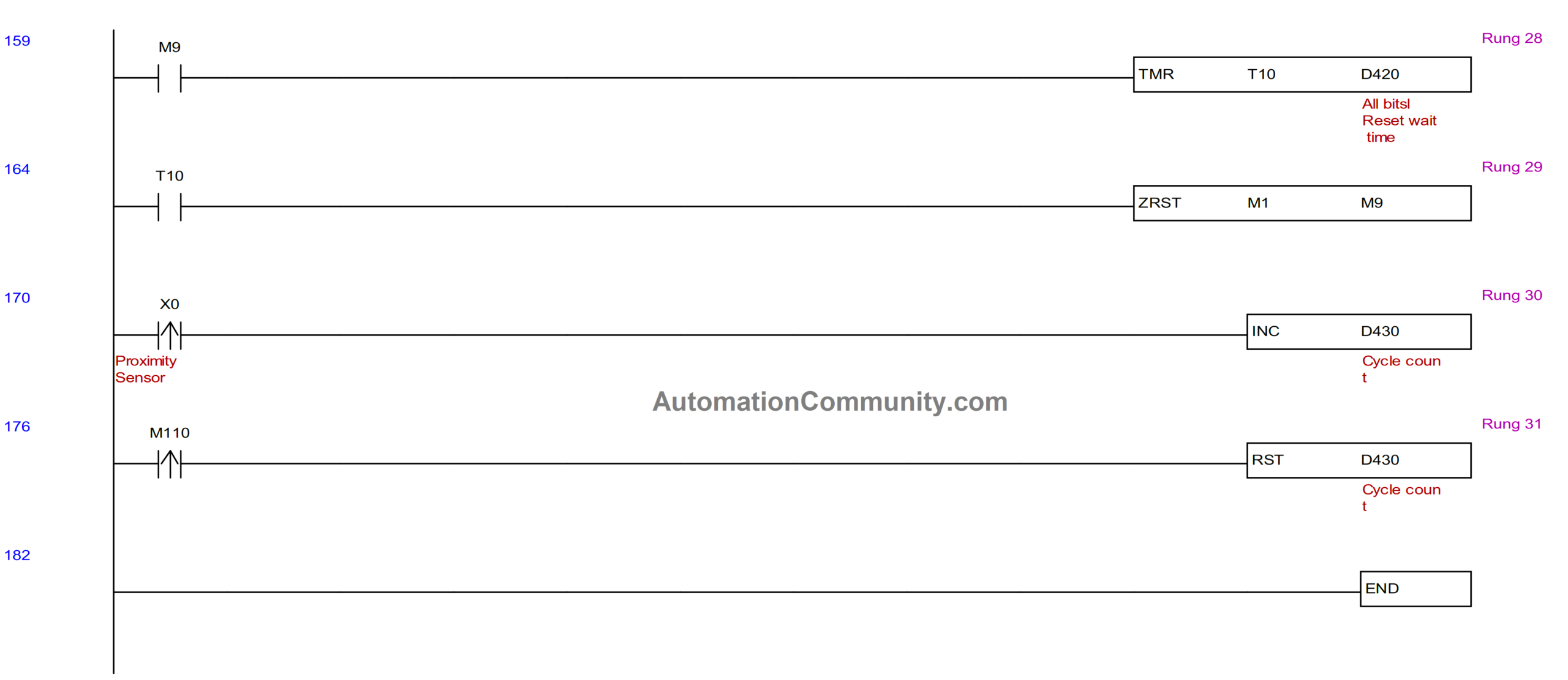
Rung 28 & 29
Timer T10 runs for its designated Pre-set time in D420 upon M9 actuation. When this period of time is up, the ZRST instruction resets all of the memory bits.
Rung 30 & 31
The last step of the machine is to drag the clay out of the machine. The clay is pushed by the piston of a pushing cylinder, which then reverses to its starting position.
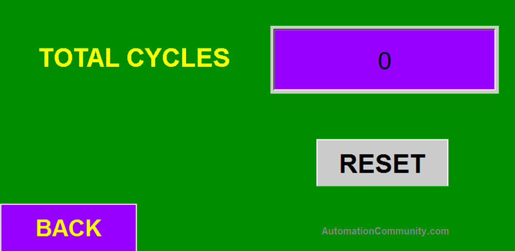
As a result, each time the piston reverses and returns to its starting position, a proximity sensor senses it and raises X0, whose rising edge is utilized to count the number of cycles in D430.
Whenever necessary, this cycle numbering can be reset to zero by pressing the momentary button identified in the HMI as M110.
HMI Program
These clays are now processed further such as drying, etc. externally.
All data registers utilized by the PLC to specify the Pre-set time for various timers are identified in the “Numeric Input” aspect of the HMI.
Make sure to have the data format as Integer 2 digits with one fractional point.
Also, the number of cycle counts is shown using Numeric Display.
The final screens of HMI are shown below:

Conclusion
Six pneumatic cylinders and two sensors are used to slice the extruded clay, add patterns to it, and divide it into ten equal pieces automatically through machine automation.
Read Next:
Suresh
April 5, 2023Good.
Vivek
April 6, 2023Very nice
Chanda Kunda
March 10, 2024Nice!
I need a PLC program for an automatic block making machine. Any help will be greatly appreciated.