Hello, engineering world, I am working as an intern in the project department of a company and I would be pleased to share my in-hand experience from my role, which can be beneficial for instrumentation/electrical engineers regarding control panels.
Control Panel Testing Procedure
Follow the below steps for control panel testing.
- Step 1: Dimension and BOM check
- Step 2: Power and Cable size check
- Step 3: Control Wiring
- Step 4: Megger and High Voltage test for the bus bar panel
- Step 5: SPP and SMPS (24)V DC check
- Step 6: VFD, PID, and TEMPERATURE controller parameter programming
- Step 7: Start Stop sequence
- Step 8: OLR, CPR, MFM, and other monitoring devices
- Step 9: PLC Programming checking
- Step 10: Documentation for panel
Let’s explore the testing procedure for motor control center (MCC) and PLC panels as per the application used, they are meant for.
A technician should be well capable enough to understand the electrical drawing and logic used for performing specific tasks. So that he/she can take adequate corrective action if there is some error while testing the panel.
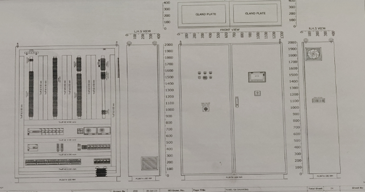
Step 1: Panel Dimensions and GA checking
Technicians are provided with electrical drawings where all the dimensions are mentioned as per the client’s requirement.
All dimensions of the panel, plinth dimensions, cable entry, and handle hole diameter.
Step 2: Power and Cable size check
This is an important procedure as power wiring provides power to the instruments and if this goes wrong then the instrument may get damaged due to heavy flow of current or wrong wiring (DC devices powered with 230V AC supply via SMPS).
So, Instrument rating checking and color coding of wire checking becomes important to avoid such accidents.
Cable sizing depends on the current capacity of the panel. Here are some briefs for sizing and the current capability of wire
| No. | Size SQ. MM | Configuration | AMPS |
| 1 | 0.50 | 16 wire of 0.2 mm | 5 |
| 2 | 0.75 | 24 wire of 0.2 mm | 8 |
| 3 | 1.00 | 32 wire of 0.2mm | 13 |
| 4 | 1.50 | 30 wire of 0.25mm | 17 |
| 5 | 2.50 | 50 wire of 0.25mm | 24 |
| 6 | 4.00 | 56 wire of 0.3mm | 29 |
| 7 | 6.00 | 84 wire of 0.3mm | 38 |
| 8 | 10.00 | 140 wire of 0.3mm | 52 |
| 9 | 16.00 | 126 wire of 0.4mm | 70 |
| 10 | 25.00 | 196 wire of 0.4mm | 88 |
| 11 | 35.00 | 276 wire of 0.4mm | 112 |
| 12 | 50.00 | 396 wire of 0.4mm | 146 |
| 13 | 70.00 | 360 wire of 0.5mm | 216 |
| 14 | 95.00 | 480 wire of 0.5mm | 262 |
| 15 | 120.00 | 608 wire of 0.5mm | 310 |
| 16 | 150.00 | 750 wire of 0.5mm | 355 |
| 17 | 185.00 | 931 wire of 0.5mm | 415 |
| 18 | 240.00 | 1200 wire of 0.5mm | 500 |
| 19 | 300.00 | 1500 wire of 0.5mm | 550 |
| 20 | 400.00 | 2013 wire of 0.5mm | 590 |
Color code:
Power wiring
| AC Phase | Black |
| AC Neutral | Light Blue |
| DC Phase | Black |
| DC Neutral | Light Blue |
| Earth | Green & Yellow |
Control wiring
| AC Phase | Red |
| AC Neutral | Light Blue |
| DC Phase | Red |
| DC Neutral | Light Blue |
| Earth | Green & Yellow |
| Analog Input | White |
| Analog Output | Black |
| Digital Input | Brown |
| Digital Output | Grey |
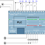
Step 3: Control Wiring
After checking power wiring and cable sizing, control wiring checks comes into play where logic authenticity decides the performance required for getting the desired output.
Here comes the interlocking, auto/manual, sequencing, and many other concepts. So, technicians must be well-versed in all such concepts.
Control wiring checking must be carried out carefully so that the final functionality of the PLC panel did not get affected.
Step 4: Megger and High Voltage Test for the Bus bar
Megger test and HV (high voltage) test are used to verify the condition of the busbar. The Megger test is used to measure installation resistance so that insulation breakthrough can be determined into the bus bar.
This is accomplished by measuring the resistance between any phase of the motor and the ground provided in the panel. If there is any fault in the insulation then there is a negative change in resistance.
For a good megger test, you should achieve a 1 giga-ohm result. Which is considered the best result at my company.
The above procedure was performed without power. Let us move on to check the power.
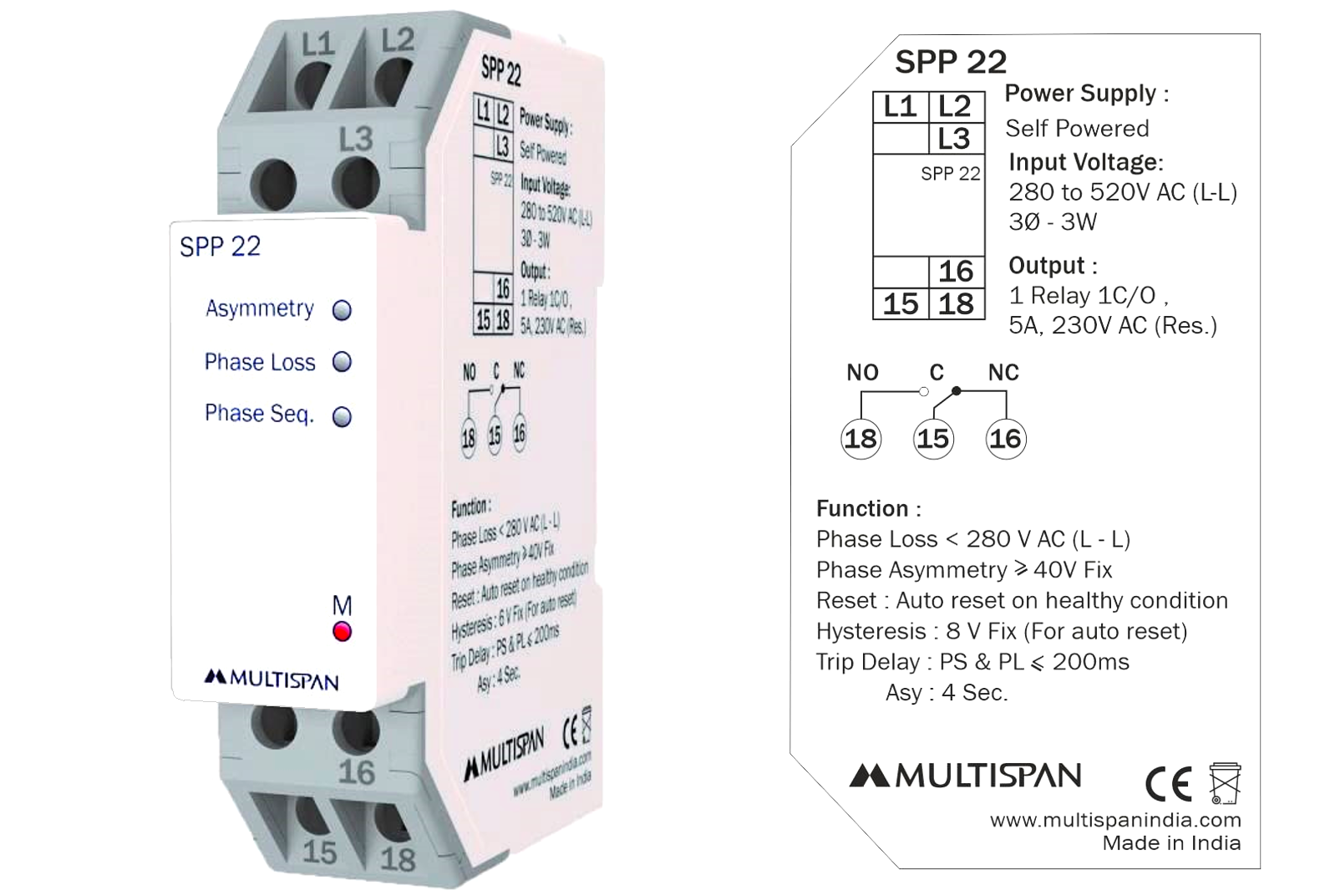
Step 5: SPP and SMPS Check
SPP (SUPPLY PHASE PROTECTION) should be set as it gives protection to the motor from negative voltage and phase loss for the electrical MCC panel.
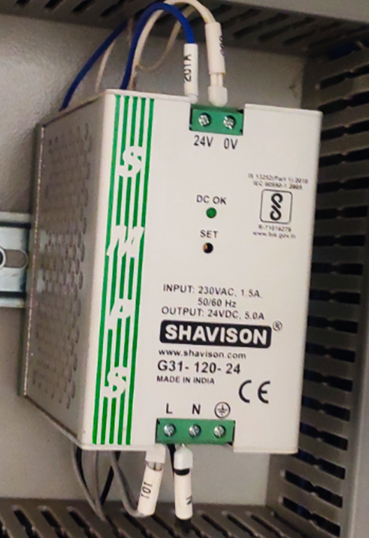
SMPS (SWITCHED MODE POWER SUPPLY) is the most important instrument when it comes to the PLC panel.
Checking the output of SMPS becomes important as it will power up PLC CPU and other analog and output module which supports the 24 V supply.
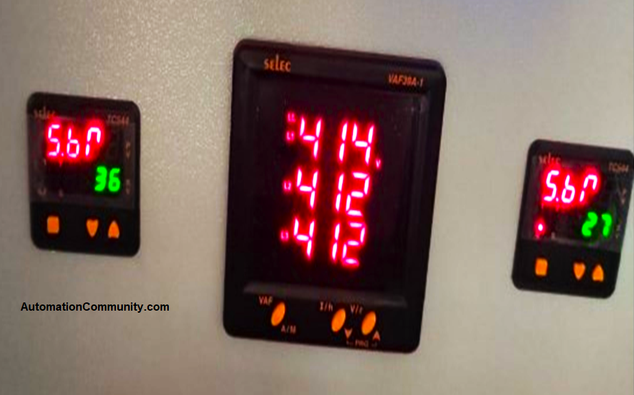
Step 6: VFD, PID, and TEMPERATURE Controller Programming
In this panel, we used the VFD, PID, and temperature controller and do their parameter settings.
The VFD is used for the smooth starting of the motor and control of other parameters such as required speed as per process application. Program the VFDs according to the rating of motors like motor full load current, frequency, acceleration-deceleration time, voltage, and HP rating, and also follow the required logic if any.
Here we used a PID controller (hardware module) in addition to the PLC. PID parameter setting should be considered if we have output from the process control element to drive the specific output.
The PID controller (standalone hardware) gets a command from the logic written in the PLC program and operates according to it.
For example, if we have a control valve operating at 50% then PID will generate the 50% signal output from the PLC command.
Step 7: Start Stop Sequence
The start/stop sequence is the essential process as it will be used to control the machine operation.
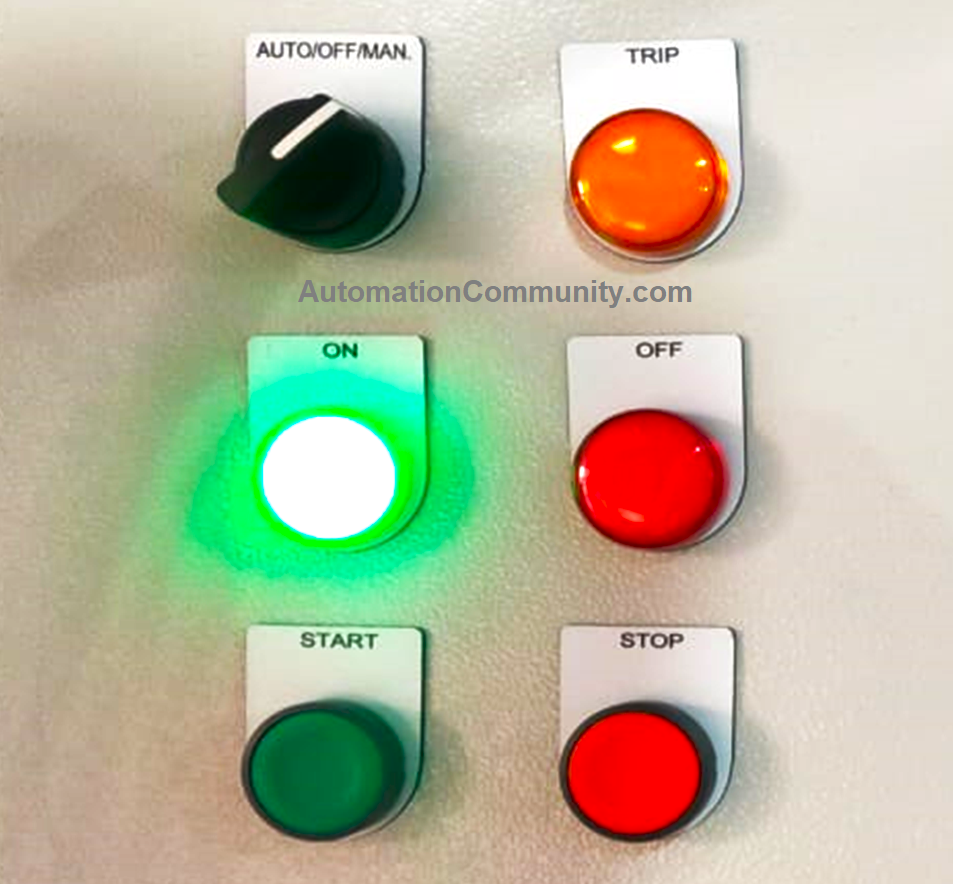
This step has two modes of operation, one is manual and the other is auto where the signal is generated from the PLC command as per the operator inputs.
Step 8: OLR, CPR, MFM, and other Monitoring devices
Set the OLR according to motor rating (hp)
CPR and MFM according to CT rating
MPD according to motor rating
This all-monitoring device comes with various brands and provides perks it for easy monitoring.
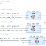
Step 9: PLC Testing
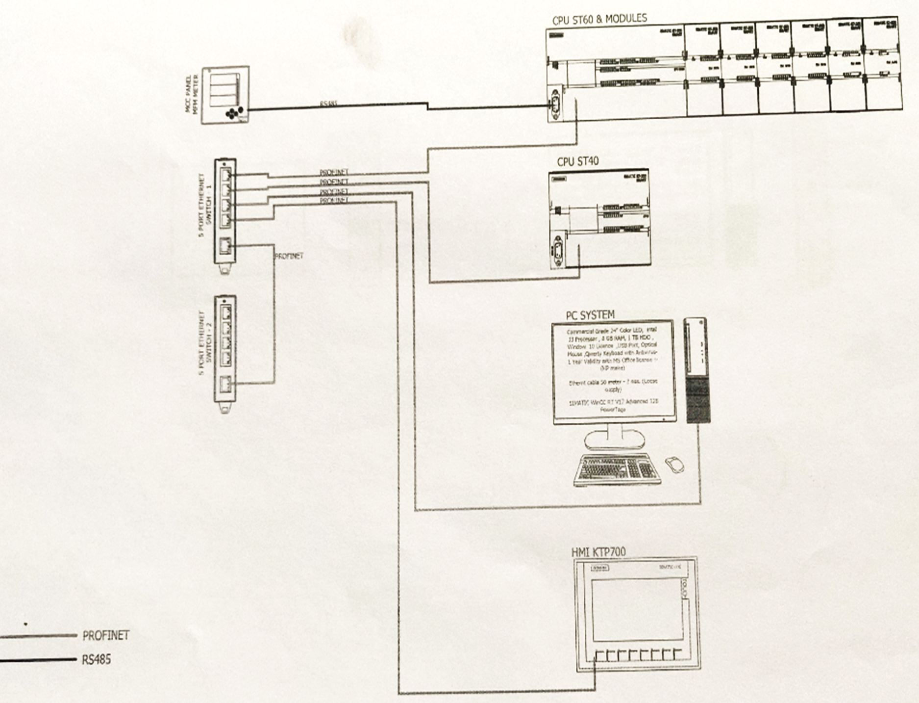
This step is especially performed by the PLC engineer. Here choose the required PLC brand such as Simetic 1200, Allen Braldey, Delta, Omron, etc.
After the selection of PLC, logic is prepared and process sequence logic is prepared in ladder logic or any other language as per the client’s interest.
After that downloading and uploading of PLC program is performed from Profinet or RS 232/485 communication protocol.
Here check the DI/DO from the watch table or give a force start command from PLC. As well as we can check it from the SCADA from where the pop-up button is provided for the specific instruments/process.
Now check the AI by using a source meter. The technician should simulate the 4-20mA of all the analog inputs. After getting the raw counts in PLC and check with the desired value.
We measure the count by applying the 4-20 mA source from the source meter. Then the logic is tested, and check for any interlocks performance, or any sequence testing if needed.
For output testing, in the PLC program, we simulate the respective outputs or force the output channel and check the field instrument such as control valve status, VFD reference speed inputs, etc.
After this, all the logic is tested. When all the terminal checking is done then check the various alarm parameter as per the configuration in PLC.
Emergency stop functions are checked and fault reset parameters are tested. After all these steps, then PLC is ready for application.

Step 10: Documentation for Control Panel
Documentation of PLC such as test report prepared by the engineer that contains various parameters such as checking panel with power and without power results.
The parameter of VFD is mentioned for the client.
The final PLC Terminations details are provided.
Inspection reports are mentioned.
Then merge all the documents and sent them to the client. This makes the panel ready to perform the commissioning at the industrial site.
Happy learning.
Read Next: