Industrial automation has many types of processes in it. Be it food and beverage, pharmaceuticals, chemicals, rubber, etc. each and every industry today uses industrial automation in it for executing tasks smoothly and efficiently. When we work in any of these industries, we find a very common application in all of them and it is an air handling unit or AHU.
The Air Handling Unit is equipment that is used to control the temperature and humidity of the air surrounding a particular area. This makes it feasible for people to work in an environment. It is to be noted that AHUs also implement PLCs in it for automating the process.
In this article, we will learn how to control an Air Handling Unit (AHU) process using PLC logic.
What is Air Handling Unit?
AHU as discussed earlier stands for an air handling unit. AHU is a large box-shaped unit that has all the essential components for ventilating and cooling the air around us. You must have seen in malls that the air around us comes from large vents or ducts installed over the top of us. These ducts are the carriers of air passed by AHU.
AHU is generally installed on the rooftop. Apart from cooling the air, an AHU also performs other tasks like filtering the air (removing and exhausting dust, smell, and other particles) and maintaining humidity. In short, the quality of air is maintained as per human index breathing.
Components of Air Handling Unit
Refer to the below image for understanding. There are many components in an AHU, but in general, the most used ones will be referred to here. As discussed before, an AHU is a box-type component, inside of which the elements required to maintain air quality are present.
The process starts with sucking air from the room (return air), passing it through chilled water coils (heat exchanger), heater, and then finally, back to the room (supply air).
Related to this, we will develop a PLC logic for it. Let us understand each of the components properly.

Temperature and Humidity Sensor
The temperature and humidity sensor is the most integral part of AHU control. When you are controlling and modulating some parameters, you will need to get the feedback of that parameter first, meaning closed loop control here. In AHU, this task is achieved by two types of sensors – temperature, and humidity.
As the air is taken from the return side for treating it, the sensors are installed at the return ducting side in the room. They will thus give you the return air temperature and humidity readings.
Filter
There are many types of filters used in an AHU like Hepa-filter, pre-filter, and fine-filter. Their task is to clean the air on two sides – one before entering the AHU and one after leaving the AHU. This ensures the removal of particles in the air and AHU.
Return Blower
The return blower is a motor-run blower that is used to maintain the flow of air in the whole room, as well as the unit. The blower will take air from the return side and throw it into the unit with full force.
Blowers form an essential part of maintaining the CFM (cubic feet per minute; meaning how many cubic feet of air pass by a stationary point in one minute) of air in the room.
Chilled Water Coil
These are the coils through which chilled water flows. Due to heat exchange, the warm temperature of the air is passed to the cooler side of the water. The output will be relatively cooler air and warmer water in the coil outlet. The water is supplied through chillers.
So, its main purpose is to maintain the temperature of the air. The passage of water through coils is controlled by a chilled water valve. This valve will modulate its opening and closing to control the temperature of air by passing the required amount of water through coils.
Heater
The heater is used to maintain the humidity of the air. This is done by absorbing the moisture content of air by heating. Its heating needs to be modulated by taking the reference of humidity. This maintains the moisture content of the air.
Supply Blower
The supply blower is a motor-run blower that is used to maintain the flow of air in the whole room, as well as the unit. The blower will throw air from the heater output into the room with full force.
Blowers form an essential part of maintaining the CFM (cubic feet per minute; meaning how many cubic feet of air passes by a stationary point in one minute) of air in the room.
Supply blowers are not always used; it is depending upon the requirement. Generally, the return blower does this task and it is a compulsory part of the unit, then a supply blower.
PLC IO’s for AHU Control
Now that the role of AHU has been understood, we will discuss the PLC inputs and outputs which will be used to control the process through PLC.
Digital inputs will be –
- auto manual switch,
- emergency stop,
- filter-1 differential pressure switch,
- return blower run feedback,
- heater run feedback,
- supply blower run feedback and
- filter-2 differential pressure switch.
Digital outputs will be –
- return blower run command,
- heater run command,
- supply blower run command, and
- hooter.
Analog inputs will be –
- temperature sensor and
- humidity sensor.
Analog outputs will be –
- chilled water valve reference,
- heater reference and
- return blower VFD speed.
Air Handling Unit (AHU) Logic
Refer to the below flow diagram on why we used these IOs and generally, we will understand the air handling unit logic through it easily then.
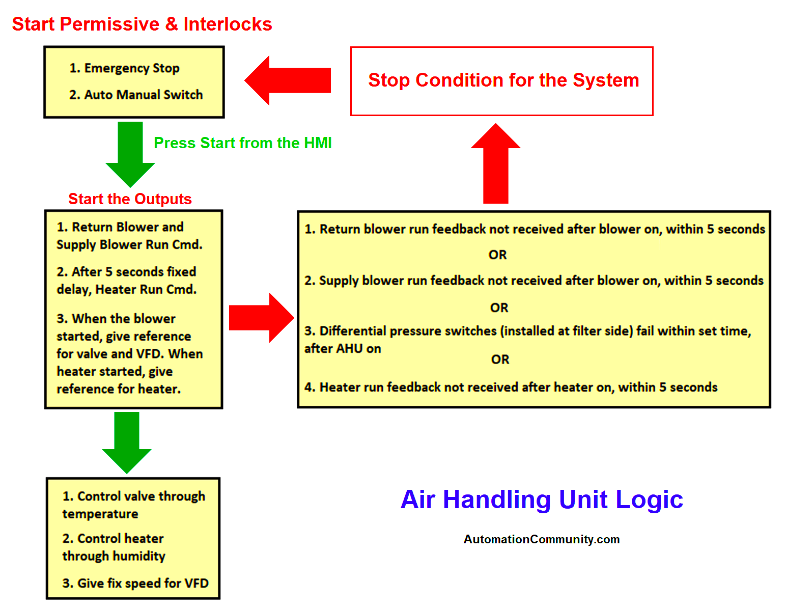
Note: A differential pressure switch is used at the filter side to check whether the filter has been choked or not. This is done by comparing air pressure between input and output.
Air Handling Unit PLC Programming
Now, let us build the logic for controlling an AHU, by referring to the flow diagram we developed earlier.
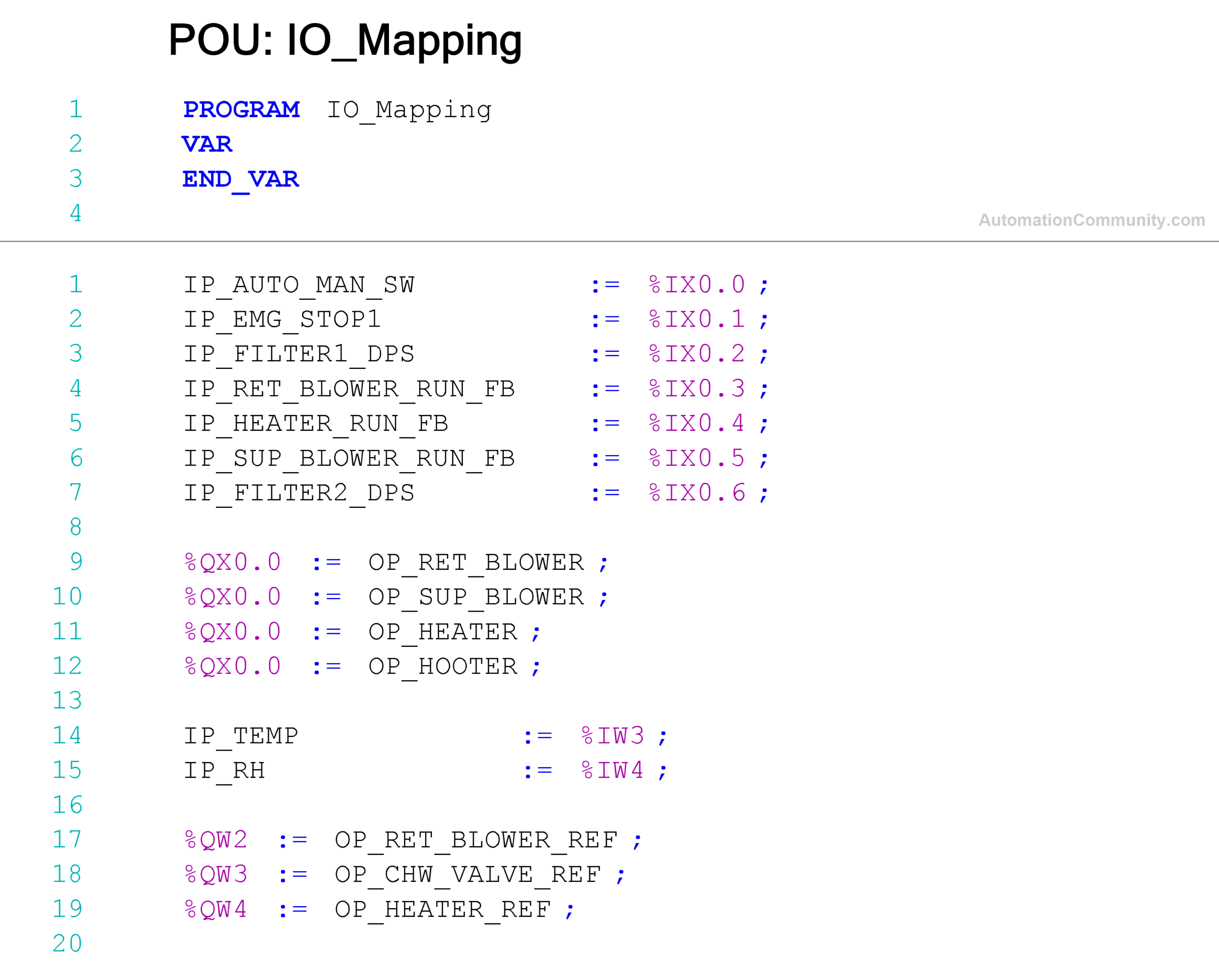
First, we will map the PLC inputs and outputs. IO mapping is the first step in developing the logic because you will require it everywhere (shown below).
PLC Logic for Alarms
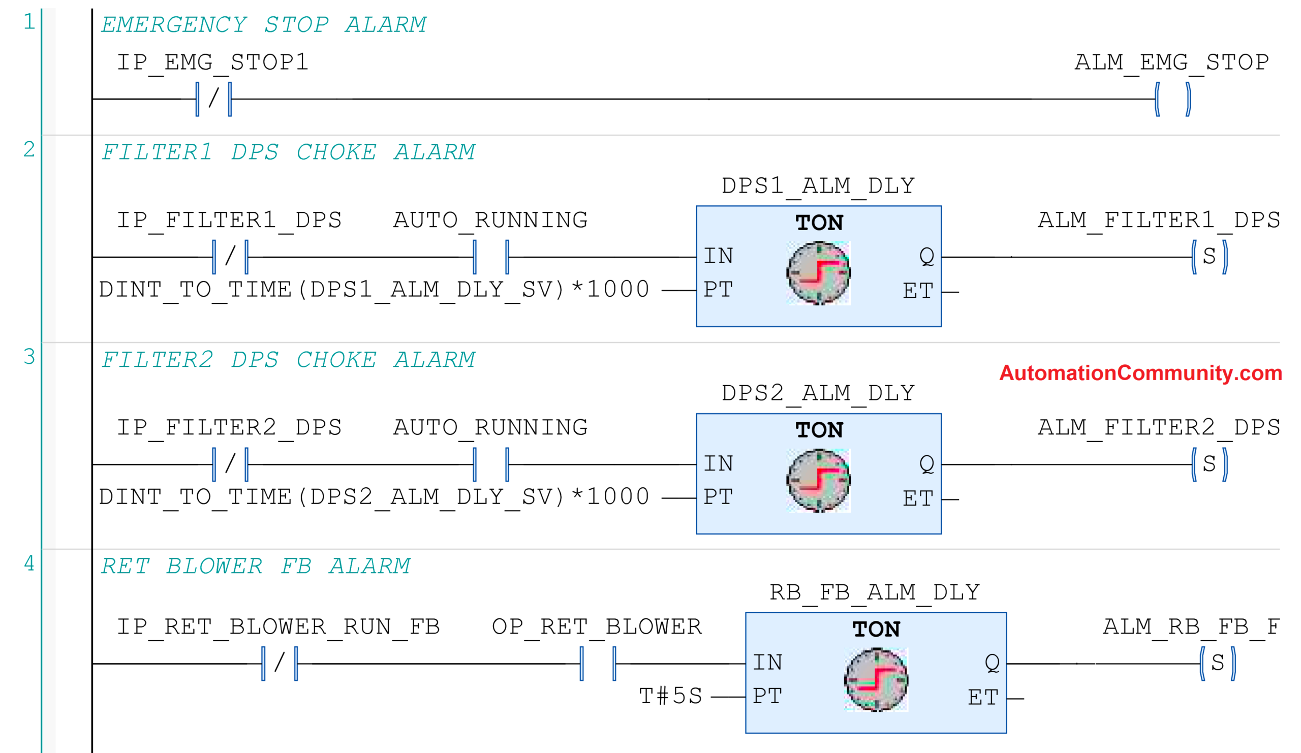
Next, we will now develop the PLC logic for alarms. This is because, when you run the auto mode logic, you will first require to keep it safe with alarm interlocks. There is a total of 7 rungs in the below image and each rung is explained below.
The first rung is for the emergency alarm, which comes immediately when the button is pressed.
The second rung is for checking the differential pressure switch (DPS-1) when the AHU is running, for a settable time.
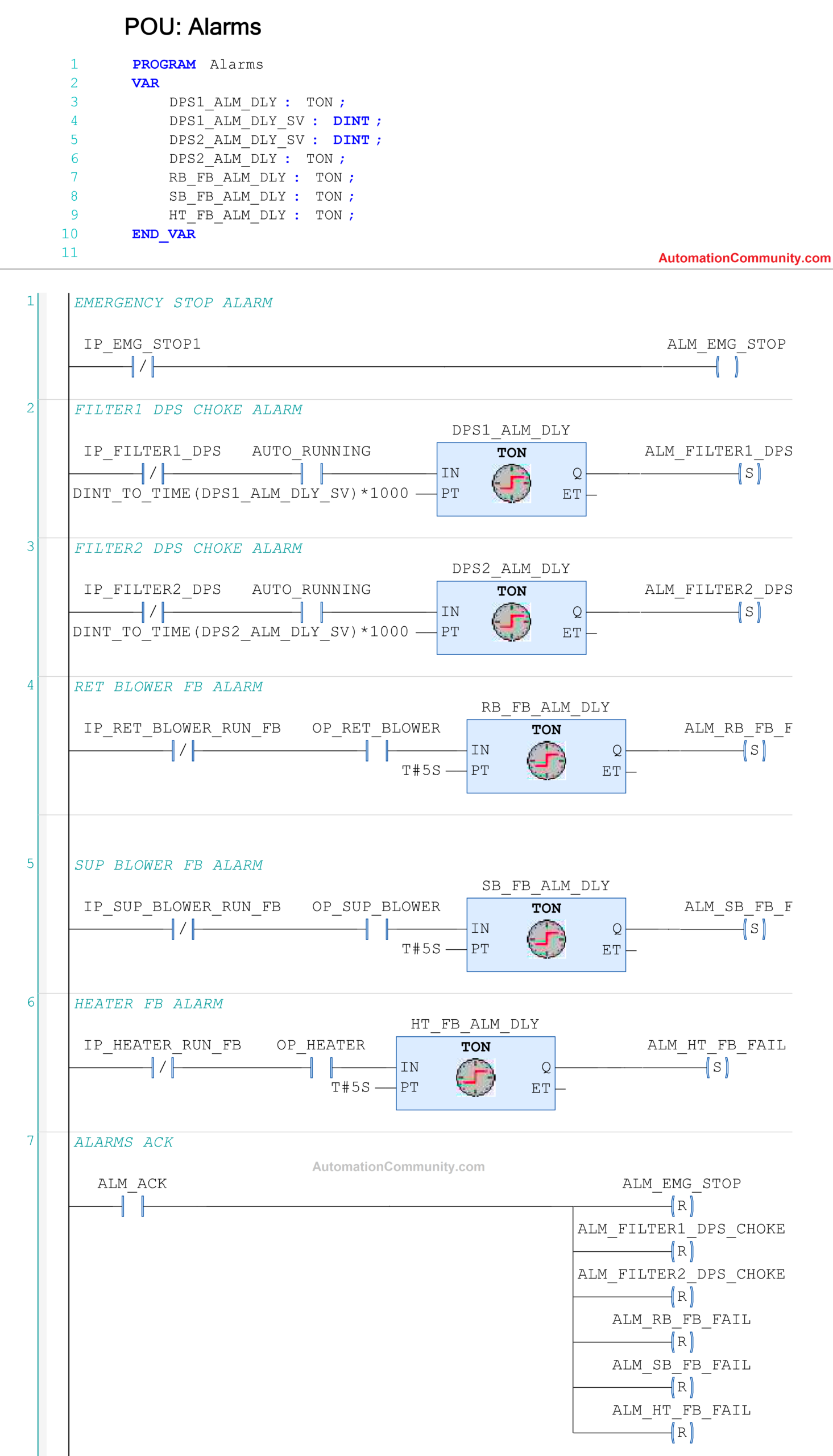
The third rung is for checking the DPS-2 switch when the AHU is running, for a settable time.
The fourth rung is for checking return blower run feedback, for just 5 seconds.
The fifth rung is for checking supply blower run feedback, for just 5 seconds.
The sixth rung is for checking heater run feedback, for just 5 seconds.
The seventh rung is used to reset the alarms.
PLC Main Logic
Now, let us start the auto mode logic in PLC.
The first rung is for starting and stopping the system.
The system is started by pressing the start button, and the system is stopped by three conditions –
- Pressing the stop button,
- Turning off the auto manual switch, or
- Any system alarm.
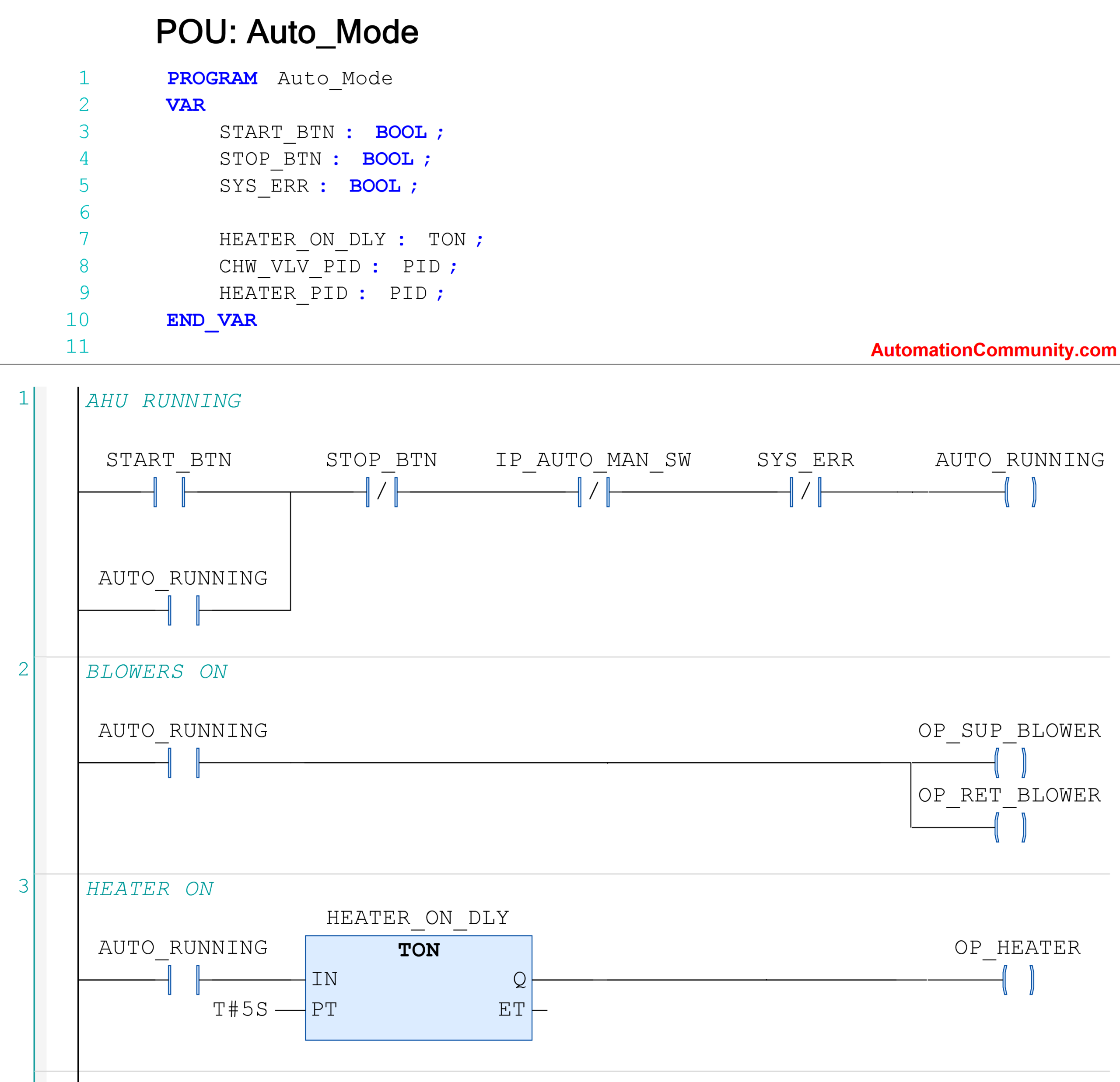
The second rung is used to start the blowers when AHU starts.
The third rung is used to start the heater after a 5-second delay.
The fourth rung is for controlling the chilled water valve through PID.
You have to set PID in such a way that when the temperature rises above the set point, the valve will open to pass more water and when the temperature goes below the set point, the valve will close to pass less water. This will maintain the temperature of the air.
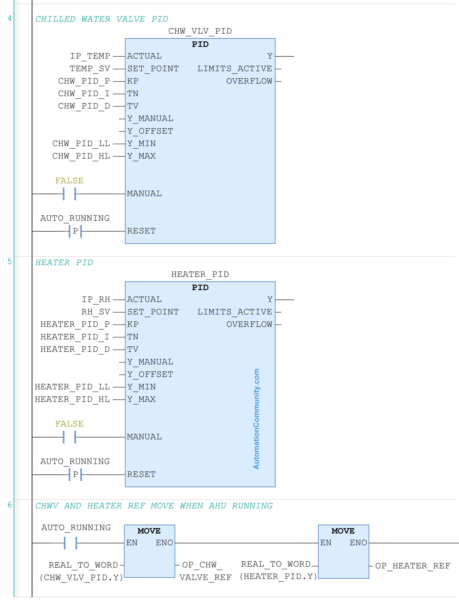
The fifth rung is for controlling the heater through PID.
You have to set PID in such a way that when the humidity rises above the set point, the heater will take more current to soak the moisture.
When the humidity goes below the set point, the heater will take less current to soak less moisture. This will maintain the humidity of the air.
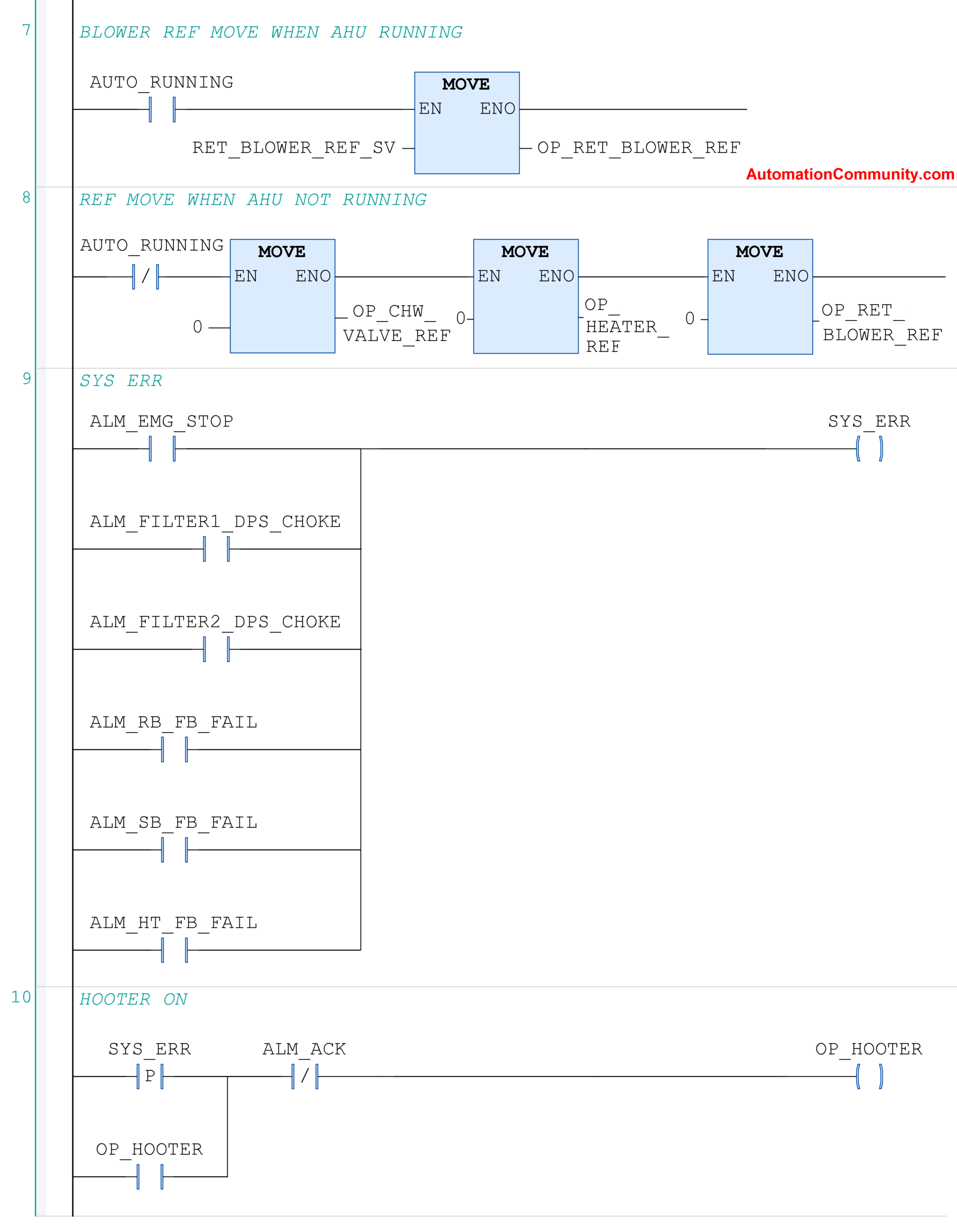
The next three rungs are for moving the analog output reference when AHU is running or stopped.
The ninth rung is used to trigger the system interlock bit when any alarm occurs in the system. And, the last rung is used to turn on the hooter when an alarm occurs.
In this way, we have seen how to write a PLC logic for an AHU. There are many components in it, depending on the manufacturer; but we have seen the most generally used one here.
Read Next: