LogixPro is a software used for learning the fundamentals of ladder logic programming. Ladder logic is a programming language used to program PLCs.
LogixPro mimics Allen Bradley’s RS Logix 500 software. This makes PLC programming easier to understand.
The Bottle Line Simulator of Logix Pro 500 simulates an automated production line that produces two different beverages.
Bottle Line Simulation in LogixPro

The I/O List in the Bottle Line Simulation is mentioned as follows.
- Conveyors
- Switches/Pushbuttons
- Sensors
- Fillers
- Gates
- Displays
Conveyors
- Main Conveyor- It moves the bottles.
- Divert Conveyor – On it, large bottles are diverted using divert gate.
- Scrap Conveyor – Broken bottles are discarded through this by using a scrap gate
Switches and Push Buttons – Start, Stop, Run
Sensors –
- LS1 – Detect the bottles
- LS2 – Detect large bottles
- LS3 – Detect broken bottles
- LS4 – Bottles are filled using a fill tube with sensor LS4
- LS5 – Large fill valve has sensor LS5
- LS6 – Small fill valve has sensor LS6
- LS7 – Bottles are capped using Cap Ram with the help of sensor LS7
- LS8 – Bottles are discarded using a scrap gate with the help of sensor LS8
- LS9 – Large bottles are diverted using divert gate with the help of sensor LS9
- LS10 – For controlling the movement of boxes
Fillers – Bottles are filled up with a large charge for large bottles and small charges for small bottles using a fill tube.
Display – There is a large as well as a small LED display to show results.
Inputs in the Program
| Start | NO | I:1/0 |
| Stop | NC | I:1/1 |
| Exist Sensor | LS1 | I:1/6 |
| Size Check Sensor | LS2 | I:1/7 |
| Broken Check Sensor | LS3 | I:1/8 |
| Fill Tube Sensor | LS4 | I:1/9 |
| Large Charge Sensor | LS5 | I:1/10 |
| Small Charge Sensor | LS6 | I:1/11 |
| Cap Ram Sensor | LS7 | I:1/12 |
| Scrap Gate Sensor | LS8 | I:1/13 |
| Divert Gate Sensor | LS9 | I:1/14 |
| Scrap Box Sensor | LS10 | I:1/15 |
Outputs in the Program
| Main Conveyor | O:2/0 |
| Scrap Conveyor | O:2/1 |
| Divert Conveyor | O:2/2 |
| Grinder | O:2/3 |
| Scrap Gate | O:2/4 |
| Divert Gate | O:2/5 |
| Fill Tube | O:2/6 |
| Large Fill | O:2/7 |
| Small Fill | O:2/8 |
| Cap Ram | O:2/9 |
| Run | O:2/10 |
| Large Bottle Count | O:4/0 |
| Small Bottle Count | O:4/1 |
| Scrap Bottle Count | O:4/2 |
| Scrap Box Count | O:4/3 |
Other Elements Required During Designing
- Timer
- Counter
- Limit Switches
- Bit Shift Left (BSL)
Bottle Line Process
- When the Start button is pressed, the conveyor belt starts moving and the bottles shift to the left one by one.
- There are three sensors that detect bottles, large bottles, and broken bottles respectively.
- Afterward, the liquid is filled in the bottles according to bottle size through a fill tube.
- Broken bottles are removed from the main conveyor through a scrap gate.
- Then caps are fixed using Cap Ram.
- Large bottles are transferred to Divert conveyor through divert gate
- The broken bottles are crushed in the grinder and filled in the scrap box.
- Once these boxes are completely filled, the scrap conveyor moves next box.
The below video demonstrates the bottle line simulation process.
PLC Program using LogixPro Simulator
The ladder logic for the bottle line process is mentioned below by the program rung-wise with the explanation of the code.
Rung 0 –
Once the programmer presses the start button the output will get energized and the simulator starts running. Here latching is provided to maintain the state until another input is received.
Rung 1 –
As the bottle gets detected by the sensor the timer gets on. It produces a delay of 10 sec and then the bottle is shifted.
This is done so that the bottles can get filled up properly and also other operations like fixing caps, discarding broken bottles, and diverting large bottles can be done appropriately.
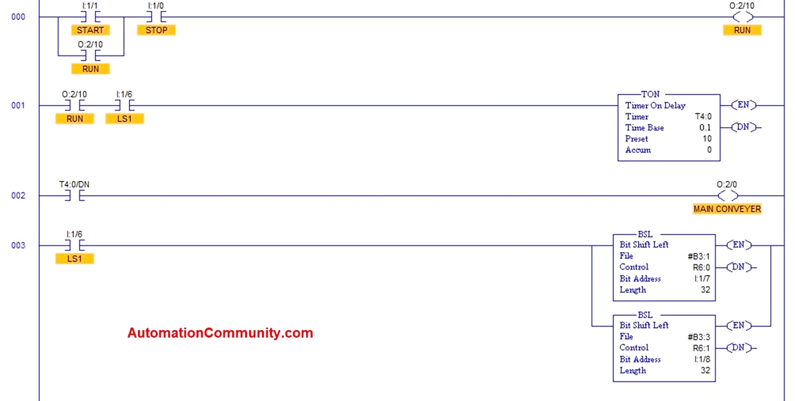
Rung 2 –
Once the delay is produced and the Done bit of the timer becomes 1 then the Main Conveyer belt starts rotating.
Rung 3 –
BSL i.e Bit Shift Left is used here to shift the bottles to left once for every low to high transition on its inputs
This helps to determine which one of the bottles needs to be filled, capped, discarded, or diverted.
Rung 4 –
LIM i.e Limit Test is used to compare specified operands to two limits which are low limit and high limit. Here this limit test specifies the time range between which the operation is needed to be performed.
Using binary bit following operations are performed here within this limit –
- Fill Tube fills the bottle (5th bottle from LS3 sensor)
- Cap is fixed (15th bottle from LS3 sensor)
- Scrap gate is opened (9th bottle from LS3 sensor)
- Divert gate is opened (5th bottle from Cap Ram)
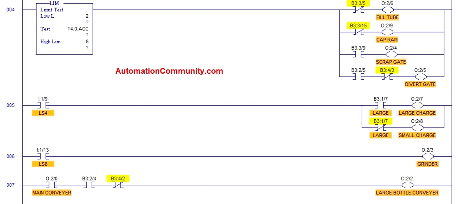
Rung 5 –
LS4 sensor determines which one of the beverages is needed to be filled in the bottle. If the bottle is large then a large charge i.e pink liquid is filled in the bottle (7th bottle from LS2 sensor).
If the bottle is small then a small charge i.e purple liquid is filled in the bottle (7th bottle from LS2 sensor). This is done using binary bits.
Rung 6 –
LS8 sensor determines that the broken bottle is discarded through a scrap gate and thus it starts the grinder for grinding the broken bottle.
Rung 7 –
As the main conveyor rotates the large bottle conveyer also starts rotating.
Rung 8 –
The grinded bottles are counted by using a counter. It counts up to 12 bottles.
Rung 9 –
When the counting is done i.e when 12 grinded bottles are filled in the box, the scrap conveyer starts rotating and the next box is placed below grinder.
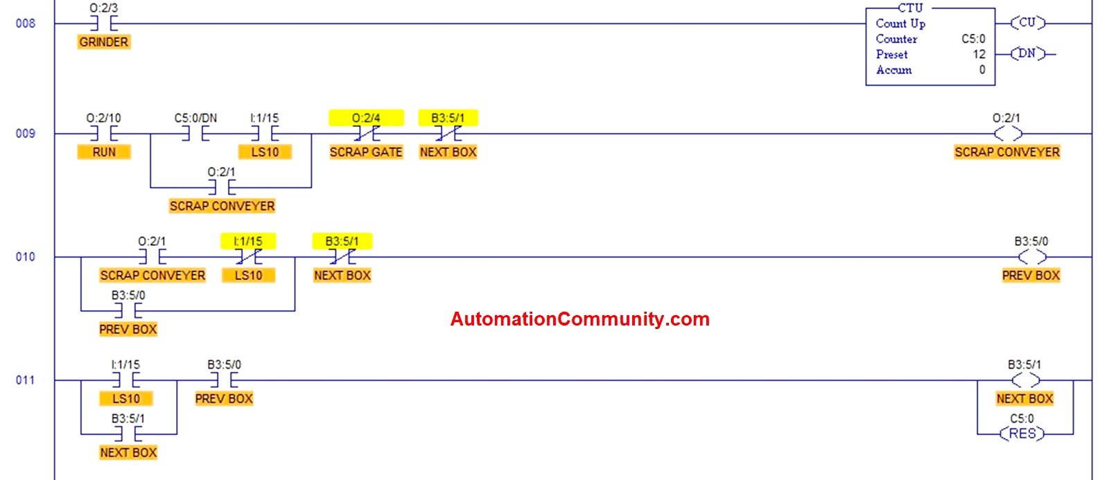
Rung 10 –
Whenever the scrap conveyor is rotating previous box which gets completely filled with grinded bottles is shifted and the next box is placed.
Rung 11 –
LS10 sensor controls the movement of the previous box and the next box. Once the next box is placed below the grinder the counter is reset and then it again starts counting.
Rung 12 and 13 –
Large bottles are counted by a counter and the count is shown on a large LED display.
TOD is used to convert the binary value of the decimal numbers to its equivalent BCD value.
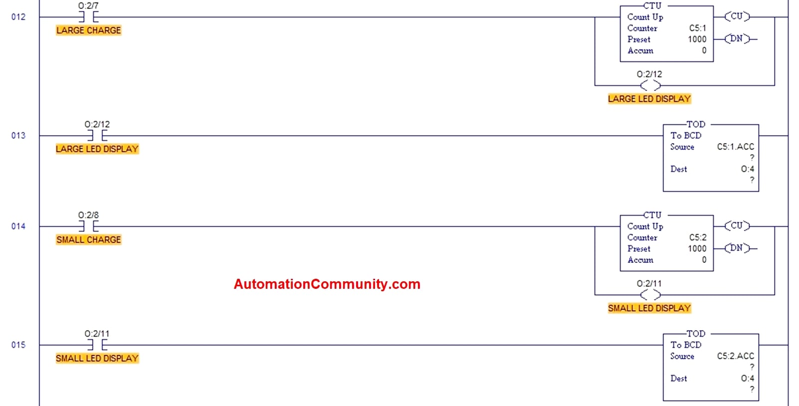
Rung 14 and 15 –
Small bottles are counted by a counter and the count is shown on a small LED display. TOD is used to convert the binary value of a decimal number to its equivalent BCD value.
Rung 16 and 17 –
Scrap bottles are counted by a counter and the count is shown on a scrap LED display. TOD is used to convert the binary value of the decimal number to its equivalent BCD value.
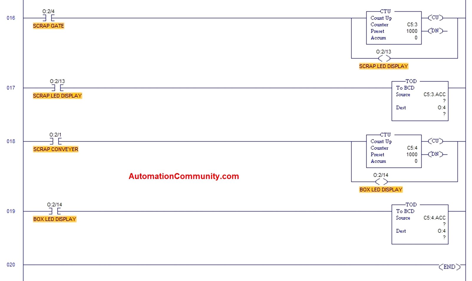
Rung 18 and 19 –
Boxes are counted by a counter and the count is shown on the Box LED display. TOD is used to convert the binary value of the decimal number to its equivalent BCD value.
Read Next:

deffjam
February 25, 2025The process description doesn’t go into much detail but the rungs description rather does. Care to correct this?