In this article we will show how we used a PLC to program a monitoring system for a fire-fighting pump room, to avoid having some reoccurring small troubles that caused a lot of very high-cost repairs.
As the name suggests, this system is only to monitor the performance of the firefighting pumps and not to control the pumps themselves. As it is another system that maybe we can mention later in a separate topic.
Fire Fighting Pump Room Monitoring System
The fire fighting pump room has 1 electric and 1 diesel pump that is supposed to run one by one in case there was a fire present in the facility to feed to fire fighting sprinklers with needed pressured water for fire fighting. The pump room has also two water tanks to provide the pumps with the needed water. These tanks are manually filled when water is below a certain limit by the system technician.
The system faced two issues before that caused a lot of damage and money to repair that damage.
Trouble 1
One of the two tanks was being filled with water, but the technician forgot to close the filling valve and went home, the tank overflowed and water started to drain out of the tank. And because the room is underground, the water level started to rise inside the room and it reached a level where it was able to go inside the electrical panel for the diesel pump controller and the all electronic cards were damaged, the room was filled with water up to 1.5 meters high and caused a lot of damage. It is worth mentioning that there is a submersible pump system inside the room, but it wasn’t able to drain all the water coming from the tank to the outside of the room.
This small trouble caused a lot of money for repairing or replacing all damaged electronics, not to mention the downtime of the fire fighting system itself.
Trouble 2
A new worker, whose not fully trained yet, used one of the fire fighting nozzles for some domestic use, but he didn’t know that his action caused the diesel pump to start running to support the water pressure of the system, he also forgot and left the nozzle open to the point that the water tank level was very low and after a while, the pumps were dry running and that caused the diesel pump to eventually be damaged. And it caused a lot of money to repair this damage.
As you can see, both times, there was no actual fire, but lack of monitoring of the pump system in addition to personnel mistakes was a reason for a lot of damages and costs.
PLC Solution
To avoid such problems, a monitoring system using a PLC was suggested. As the name indicates, the system only provides monitoring to the pump room, giving a warning when an event exists that can cause component damage or hinder fire fighting system performance.
The suggested monitoring system will behave as follow:
- A warning will be given if the water level in one of the tanks is very high or very low, this will be obtained by the use of water level switches.
- A warning will be given if the diesel pump is running or if the diesel pump control system has a fault, this will be obtained through signal communication between the pump controller and monitoring system PLC.
- A warning will be given if the electric pump is running or the electric pump controller has a fault. This will be obtained through signal communication between the pump controller and the monitoring system PLC.
- A warning will be given if there is any presence of water on the room floor; this will be achieved through the use of a water leakage sensor on installed on the walls and floor of the room.
- A warning will be given if the submersible pumps can’t drain all water below a certain level.
If you count previous points you will find that we have 10 warning signals that will be monitored by our PLC.
For outputs, we will have two main outputs which are a warning siren and a warning LED indicating there is a fault event occurring. There will be 10 LEDs one for each warning condition to indicate which fault condition is present at the moment.
System Operation
As we mentioned before the system will have no control over the fire fighting pump system, it will only monitor the behavior of the system and give warning if a fault condition is present. This will be done through the following steps:
- For physical quantities like the tank’s water levels and the water leakage sensor signals, the monitoring system will wait for 10 seconds before deciding that this event is a warning case.
- For non-physical quantities like the Pump Run signal or Pump fault signal the system will immediately acknowledge this event and trigger the warning system.
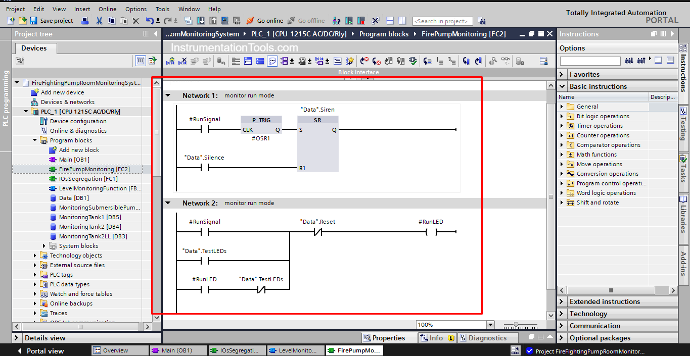
- When there is a fault condition, the siren can be stopped through the Silence Push-button.
- The warning LED for each fault condition will not be OFF unless the fault condition is cleared and the Reset Push button is pressed.
- Another Push button is provided to test all LED’s operation. When the Test push button is pressed all indication LEDs will be ON, and will stay ON until the Reset push button is pressed.
PLC Programming
IO segregation:
The first step we made in programming the system is to assign the IOs to our project.
In a previous article, we talked about a best practice called IOs segregation, which is to assign each input or output signal to trigger a tag or a marker in a global data block and then use the new defined tags throughout the whole program. See picture 1.
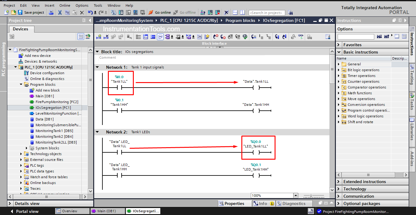
As you can see from the picture, when %I0.0 is ON it will trigger a tag Tank1LL inside the global data block named DATA. The same was done to all the IOs of the project.
Monitoring Level Function block
Next, we created a function block for monitoring the water level of fire tanks and also for the submersible pumps. We did that because the coding for all of them will be the same, so we used a function block to write the code only one time and reused it with all tanks.
Inside the FB we have created two separate logics, to monitor the LL level condition and the HH level condition. See pictures 2 and 3.
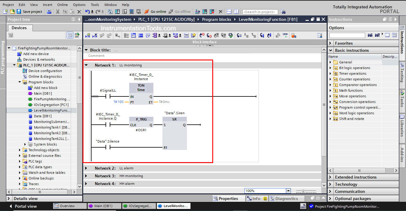
As you can see, when the signalLL is triggered, a monitoring timer will be activated and it will start counting the 10 seconds mentioned before, when 10 seconds pass, the warning Siren will be triggered.
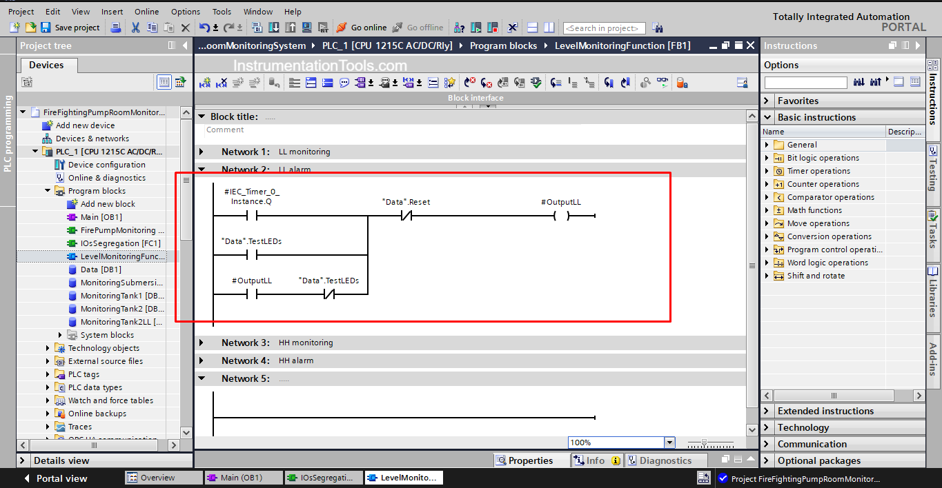
In the next network, the monitoring timer trigger will also turn on the OutputLL which is the indication LED for the related tank LL alarm.
The previous code is generic code that can be used for any tank; we just need to associate the proper parameter with the right function block call. See picture 4.
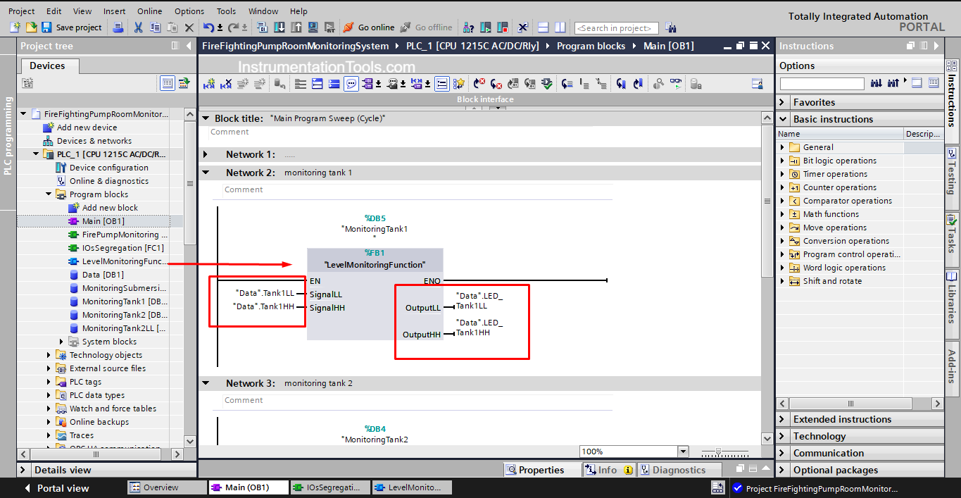
As you can from the previous picture, we dragged the FB inside the main OB1 block to call the function block. By assigning the parameters of fire tank 1 we are now monitoring the condition of tank 1.
The same can be done for tank 2 simply by calling the FB again, but this time we will assign the tank 2 parameters. See picture 5.
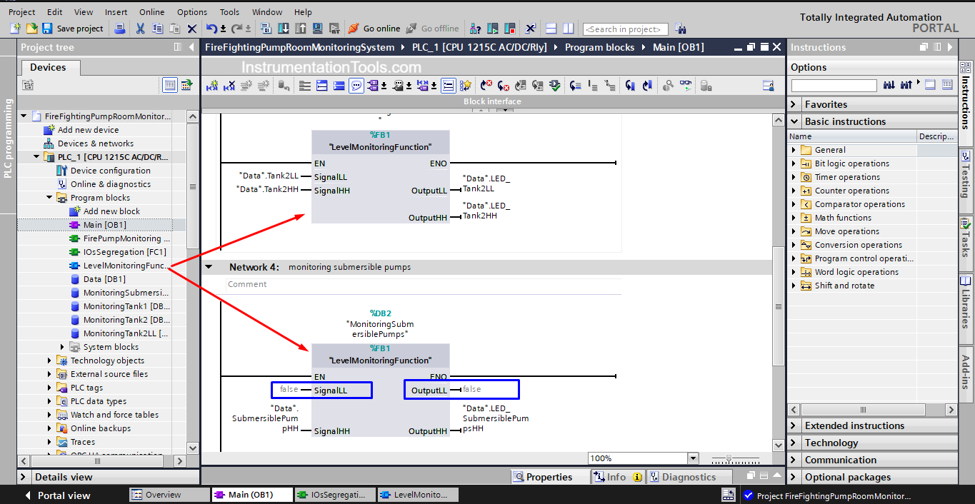
Did you notice that we used the same FB for the submersible pumps, even though we only monitor the HH level for the submersible pumps? This is real proof of why using FB n your PLC code will make it easier to write and read.
Monitoring Fire Pumps Conditions
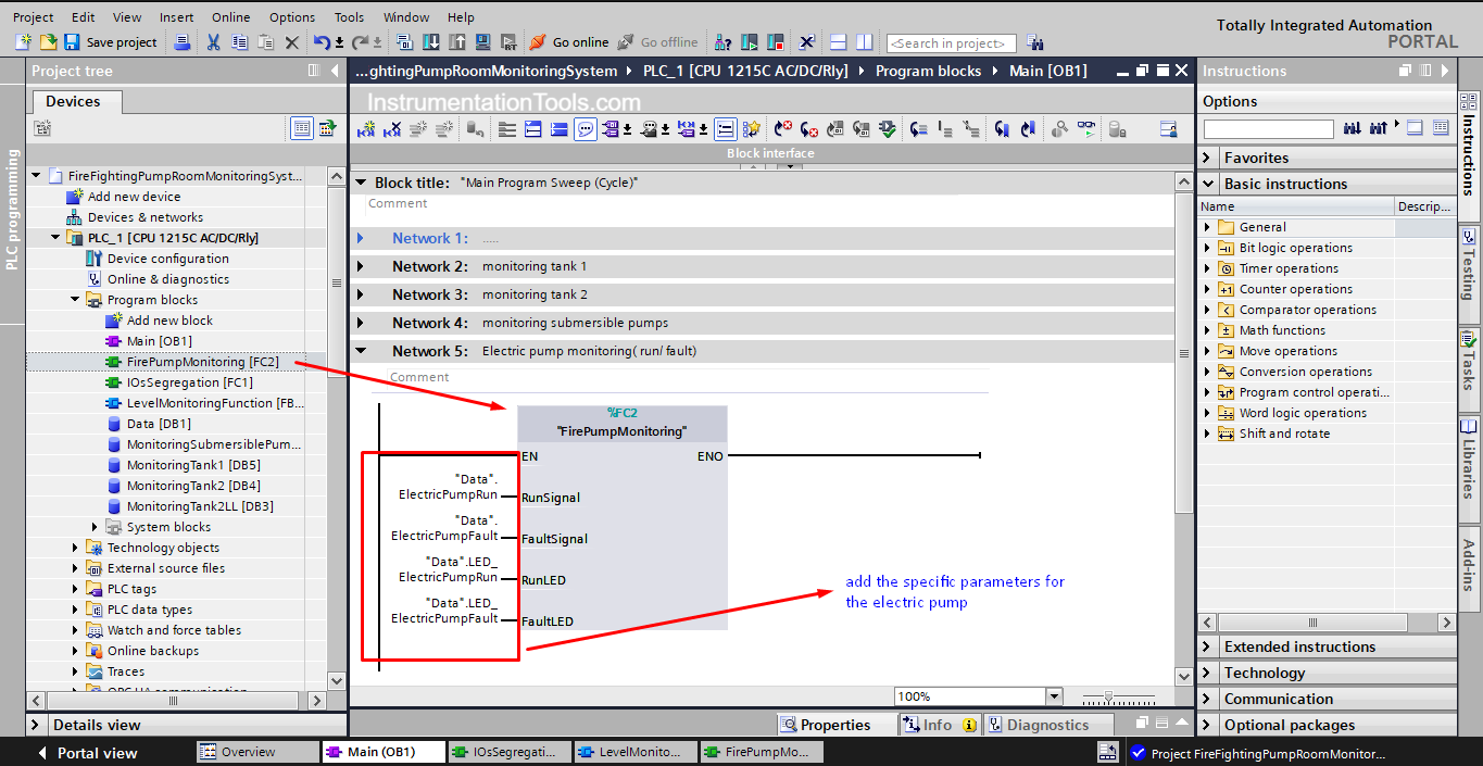
In this step, we created a function FC to monitor the run and fault conditions of the electric and diesel pumps.
We created the PLC Logic one time inside the FC and then call the FC two times for the electric and diesel pump. See picture 6.
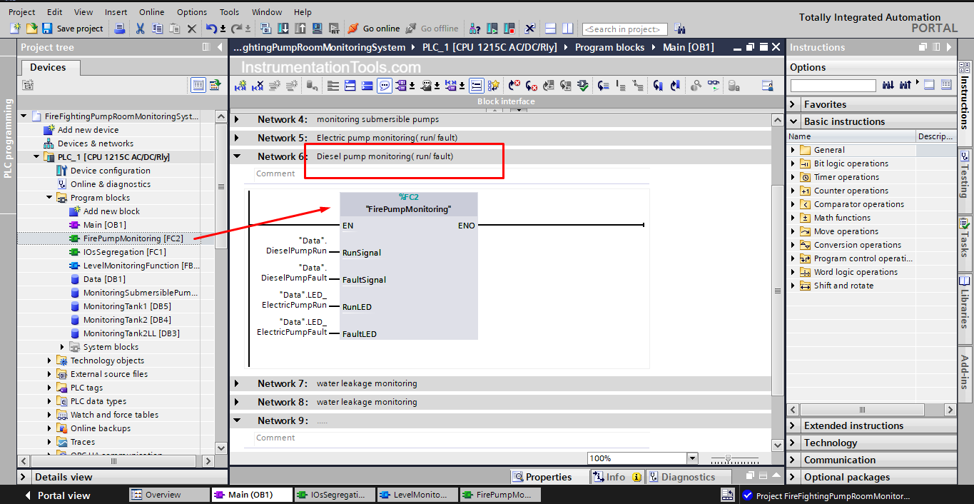
You will notice that the PLC code is similar to the previous FB, except for the monitoring timer. We want to give the warning immediately when the pump is running or has a fault condition which is why the timer wasn’t used in this case.
To use this FC with the electric pump, we simply call it inside the OB1 and assign the electric pump parameters to it. See picture 7.
We do the same for diesel pumps. See picture 8.
Monitoring the Water Leakage Sensor
The code for monitoring the water leakage sensor is the same as the code inside the FB but it doesn’t make much sense to use the code for a function block called tank water level for a leakage sensor behavior that is why it is written separately in the main OB1.
PLC Code simulation
Now we compile and simulate our project to see if we met our PLC project functionality or not.
First, we will trigger the input for the water leakage sensor but for a time less than 10 seconds. See picture 9.
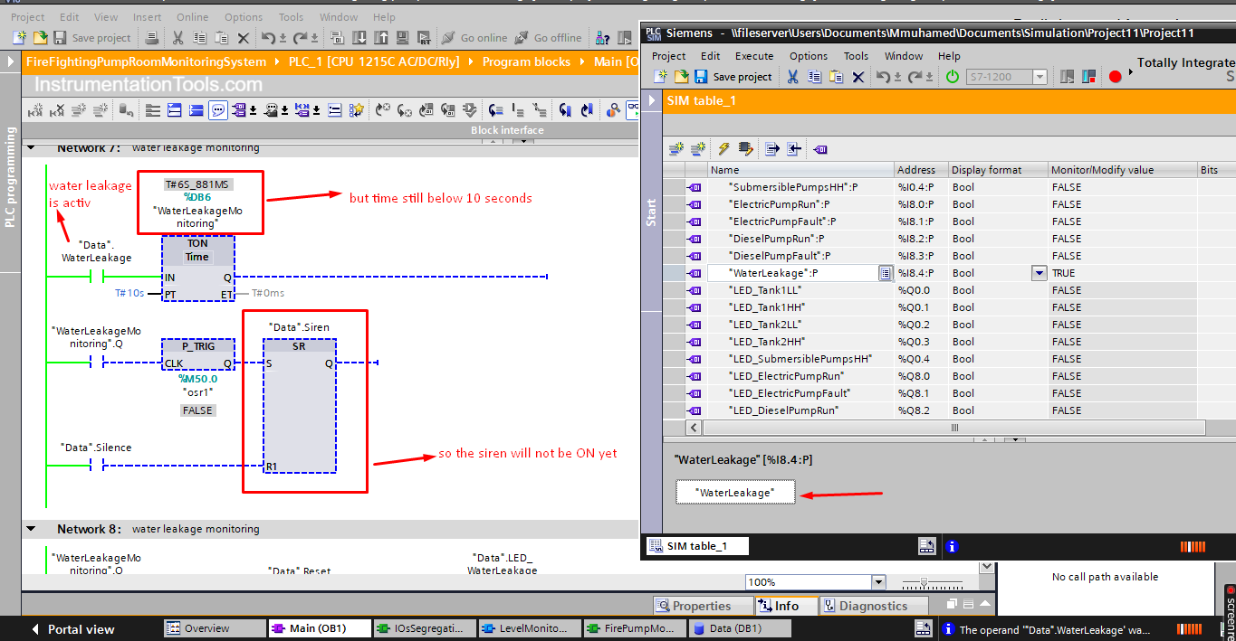
As you can see, the siren didn’t go ON because the sensor was triggered less than 10 seconds as we programmed. See picture 10.
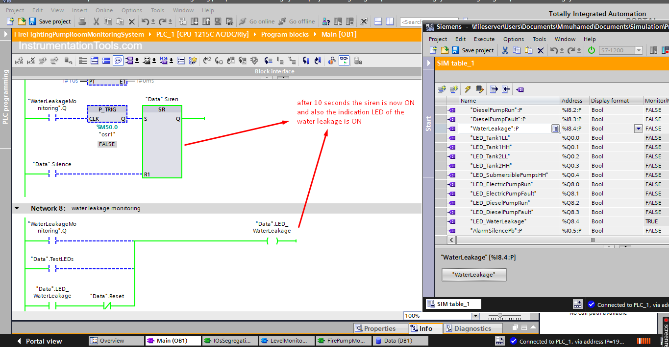
Now that the water leakage was triggered more than 10 seconds the warning siren and the indication LED are now both ON.
When the silence push button is pressed the siren should be OFF but the warning LED should remain ON. See picture 11.
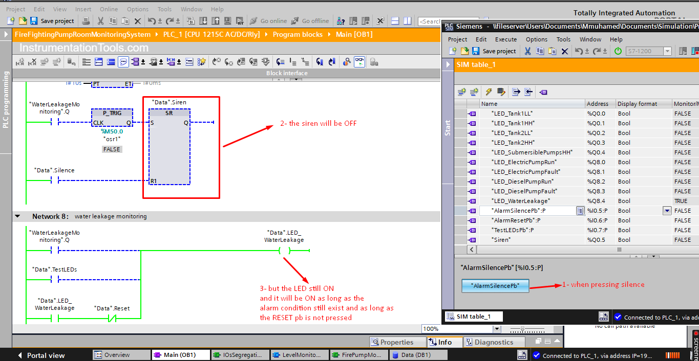
As you see, the siren went OFF when the silence push button was pressed, but the indication LED remained ON. To switch off the LED the reset push button should be pressed after the fault condition is cleared. See picture 12.
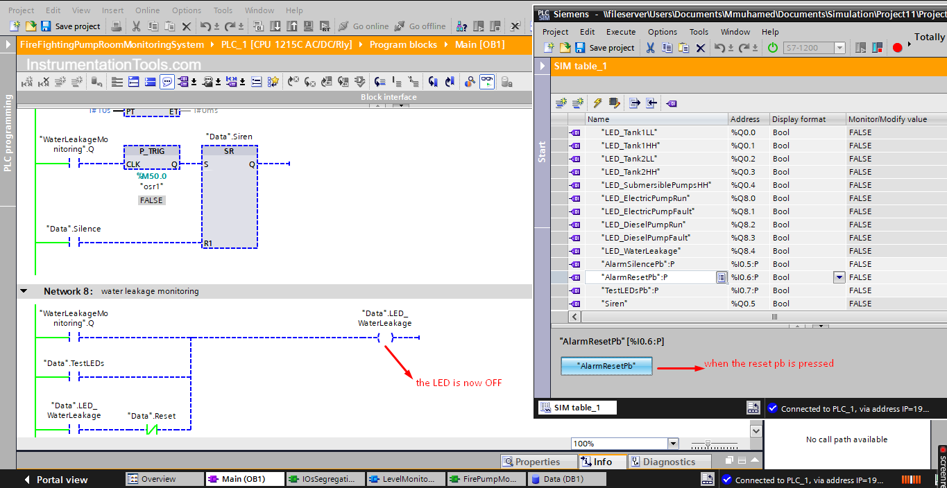
Now that the reset push button is pressed, the alarm LED is OFF, provided that the fault condition is cleared.
This was a simulation of the PLC project code for only one signal, try to run the project and simulate other fault conditions and see how the system will react.
Project Downloads
How can we improve this PLC Project?
The previous code already solve the existing problems, but there are many ways to solve the issue and even make the project better, some of these are the following:
- Use analog-level sensors instead of digital sensors.
- Adding an HMI to the project and eliminating the need for the push buttons and the indication LEDs.
- Maybe allow some control over the firefighting system and not just monitoring. Like preventing the pumps from running if the water level is LL.
Read Next: