The online machine monitoring system (MMS) is used for rotating equipment to monitor and protect the motors from critical vibration and temperatures. Before going into the topic, first, we will discuss basic parameters related to the MMS system.
Vibration is the motion of machine components caused by dynamic forces. Vibration is an oscillation defining the quantity of motion of a mechanical system.
Vibration is described in terms of Amplitude, Time or frequency, and Phase (degrees)
Transducer – Converts Vibration motion into an electrical signal for processing.
Vibration Meter – Detects only amplitude (No frequency components)
Vibration Analyzer Performs conversion of Amplitude vs Time to Amplitude vs Freq. (Spectrum Analysis, FFT, Signature)
The frequency spectrum and the time waveform help us to determine what is wrong with the machinery. These plots have the three components of vibration – amplitude, frequency, and phase.
Amplitude tells – How much it is vibrating tells us how severe its overall condition is.
Frequency tells – How often it is vibrating may indicate what machine component is causing the severe amplitude.
Phase can be used to differentiate between machine problems that have similar spectrum indications.
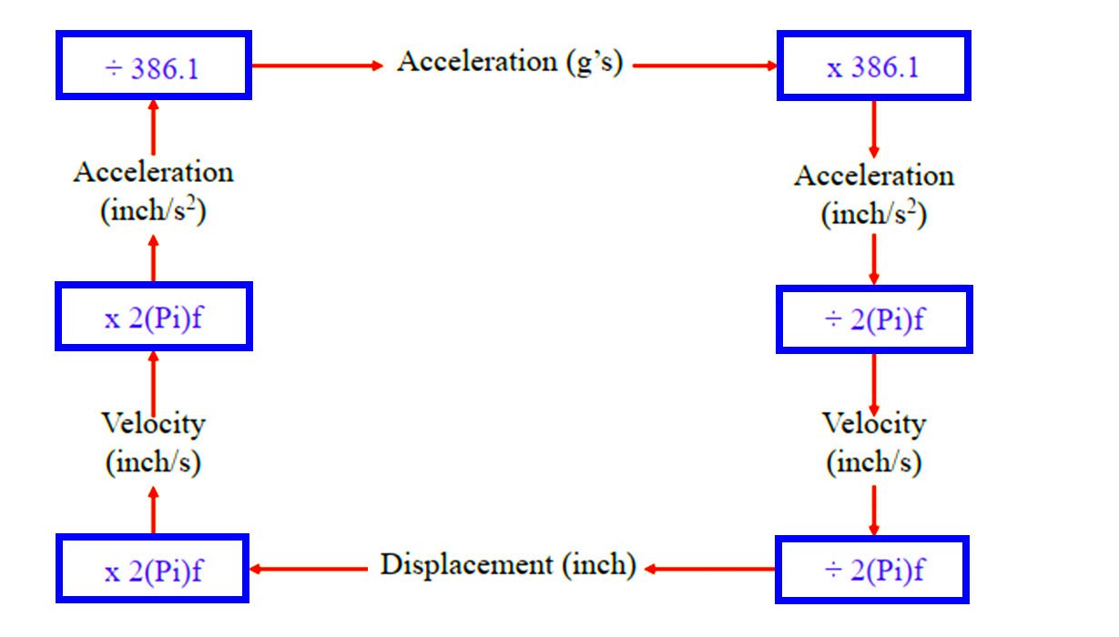
The actual physical movement of the vibrating object is known as Displacement.
Displacement is a measurement of the linear movement in the signal as the machine oscillates back and forth in its vibration. It is usually measured in Mils or microns.
1 Micron is equal to 1/1,000 of a millimeter. 25.4 Microns equals 1 Mil. Displacement is frequency related.
10 mils @ 1000 rpm are not the same as 10 mils @ 10000 rpm.
The speed at which displacement occurs is known as velocity. It is usually measured in inches per second (IPS) or millimeters per second.
Velocity is the most accurate measure of vibration because it is not frequency related. 0.5 IPS @ 1000 rpm is the same as 0.5 IPS @ 10000 rpm.
Acceleration is a measurement usually compared to acceleration due to gravity in the signal at the instant the oscillation of the vibration changes direction. It is measured in terms of meters per second per second.
Acceleration is related to frequency, in that 1 g @ 1000 rpm is not the same as 1 g @ 10000 rpm.
Acceleration = g’s rms. or peak
Velocity = inch/s rms. or peak
Displacement = mils peak to peak
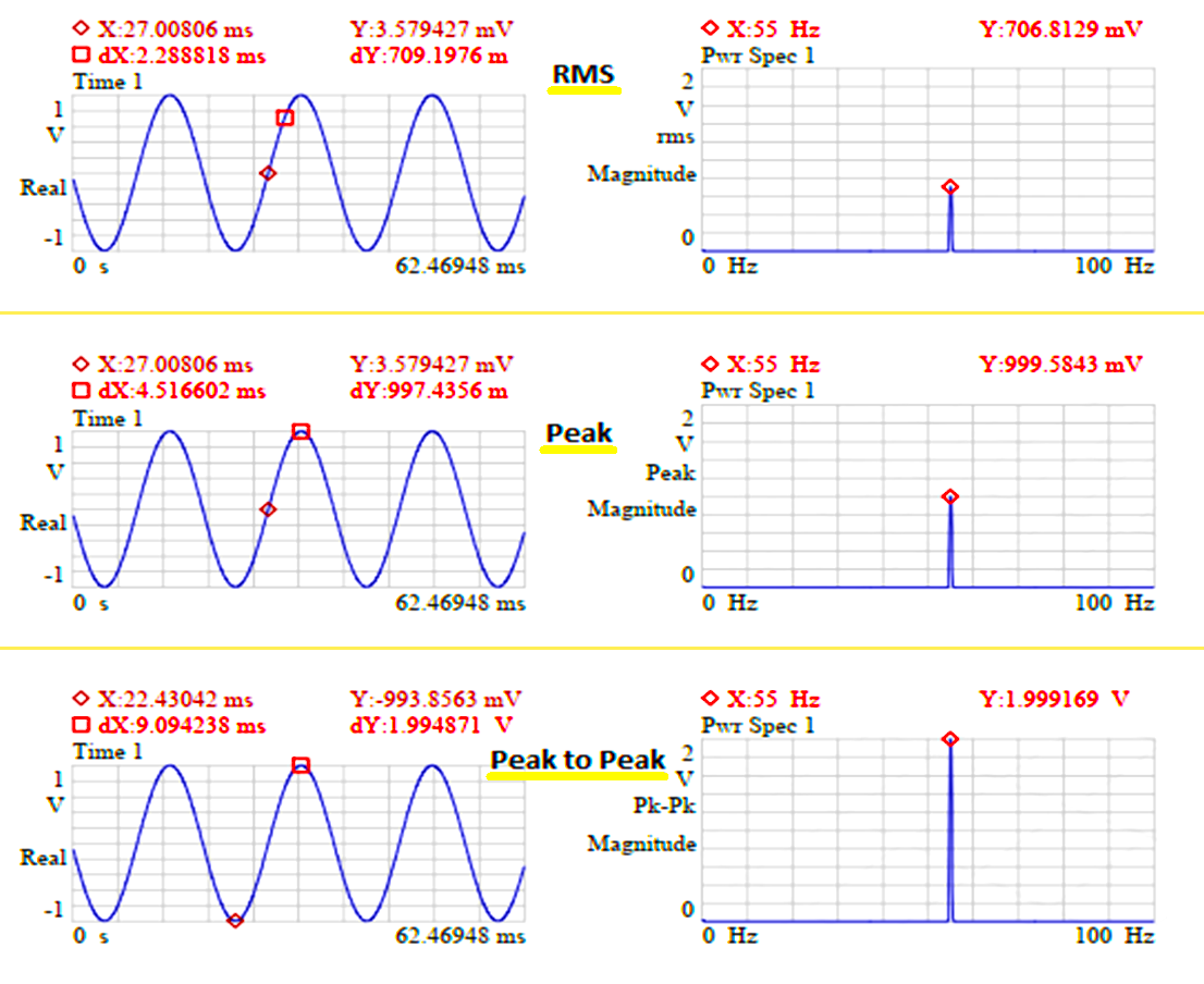
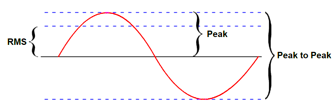
The Peak – Peak value is expressed from the peak to peak amplitude in the time waveform.
The rms. value is expressed from zero to 70.7% of the peak amplitude for a single frequency
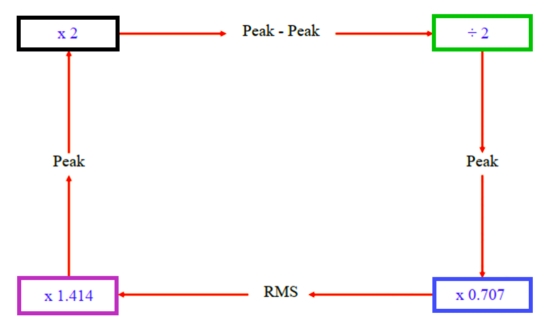
Many times it is necessary to change a value between units.
Pk-Pk / 2 = Peak
Peak x 0.707 = RMS (Peak / 1.414 = RMS)
RMS x 1.414 = Peak (RMS / 0.707 = Peak)
Peak x 2 = Pk-Pk
The acceleration value of 1 g is equal to the rate of change of speed equal to 386.087 inch/sec2 or 9806.65 mm/sec2 or 32.2 ft/sec2.
Check these online vibration value conversion tools and simulators. This will help to simulate and verify the result during testing through a high-speed recorder/frequency generator: Click Here
Causes of Vibration
The causes of vibration may be due to
- misalignment,
- looseness,
- bearing defects or wear,
- unbalance,
- Internal Component Rubbing,
- Structural Resonant Conditions, etc.
Types of Vibration
Type of vibrations are
- Periodic
- Random
- Transient
An example of periodic vibration is a mass imbalance in components so that vibration repeats itself once every time period.
An example of Transient vibration is Pump cavitation due to improper system line-up.
Vibrations caused by a rotating component are a combination of free and forced vibrations. Free vibrations are vibrations that occur naturally or on their own after an initial force is applied.
A simple example is the striking of a tuning fork. Forced vibrations occur at the rate of a repeating or a reciprocating force, as in the case of a piston or in a situation of unbalance.
Accelerometer
A 100 mV/g accelerometer will have a dynamic range of +/- 50 g’s, and a dynamic output of +/- 5 volts AC.
The main points of the accelerometer are mentioned below.
- Measures casing vibration
- Measures absolute vibration
- Integrate to Velocity
- Double integrate to Displacement
- Easy to mount
- Large range of frequency response
- Available in many configurations
- No one sensor fits all applications
Example: 330400 series accelerometer -> 10.2 mV/m/s2 (100 mV/g) 20 dB maximum. The amplitude of Resonant Peak.
Sensitivity: 100 mV/g +/‐5%
Frequency Response: +/‐3dB
30 – 900,000 CPM or 0.5 – 15,000 Hz (1 Hz = 60 cycles per minute)
Displacement Probe or Proximeter
The main points of the displacement probe or Proximeter are mentioned below.
- Non‐contact Measures relative shaft vibration
- Measures shaft center line position (DC gap Voltage)
- Measures axial position (Thrust)
- Provides Speed or Trigger
- Target material varies Output
- Simple calibration
- No one sensor fits all applications
Example: 3300 XL 8mm Proximity
Dynamic range: 10 – 90 mils (0.25 – 2.3 mm)
Sensitivity: 200 mV/mil (8 V/mm)
Frequency response: DC – 10 kHz
Velomitor
The main points of the velomitor are mentioned below.
- Self Generating – no power supply required
- The magnet inside the coil generates velocity proportional to the vibration
- Spring mass system
- 10 Hz. to 1000 Hz.
- Phase change 90 Deg
- Directional mounting
- Output = mV/inch/sec
Example: 300500 velometer
Sensitivity: 3.94mV/mm/s (100 mV/in/s)
Frequency Response: 4.5 Hz to 5 kHz (270 cpm to 300 kcpm
Machine Monitoring System

Online machinery monitoring for rotating equipment is typically divided into two categories:
- Protection Monitoring (MMS / MPS / VMS)
- Prediction Monitoring (CMS)
MMS means machine monitoring system
MPS means machine protection system
VMS means vibration monitoring system
CMS means condition-monitoring system
Sensors used in Protection Systems
The most common sensors used for protection and/or protection monitoring are:
1. Acceleration
- Accelerometer (piezoelectric-based)
2. Velocity
- Velocity sensor (piezoelectric-based)
- Velocity sensor (electrodynamic-based)
3. Displacement Position
- Eddy current sensor
- LVDT (Linear Variable Differential Transformer)
4. Displacement vibration
- Eddy current sensor
5. Rotation Speed and Phase
- Eddy current sensor with phase target
- Hall effect sensor with phase target
- Optical sensor with optical target
6. Rotation Acceleration
- Eddy current sensor with gear target
7. Rotation Direction
- Dual eddy current sensors with gear target
8. Temperature
- Surface temperature in tandem with an accelerometer
- Infrared note: infrared is not typically used with an online system
9. Pressure
- Static and dynamic pressure sensor
- Dynamic pressure sensor
10. Sound
- Ultrasound detector
Some of the specialized measurements for turbine supervisory instrumentation (TSI) include differential expansion, eccentricity, zero speed, case expansion, shaft absolute, and Valve position.
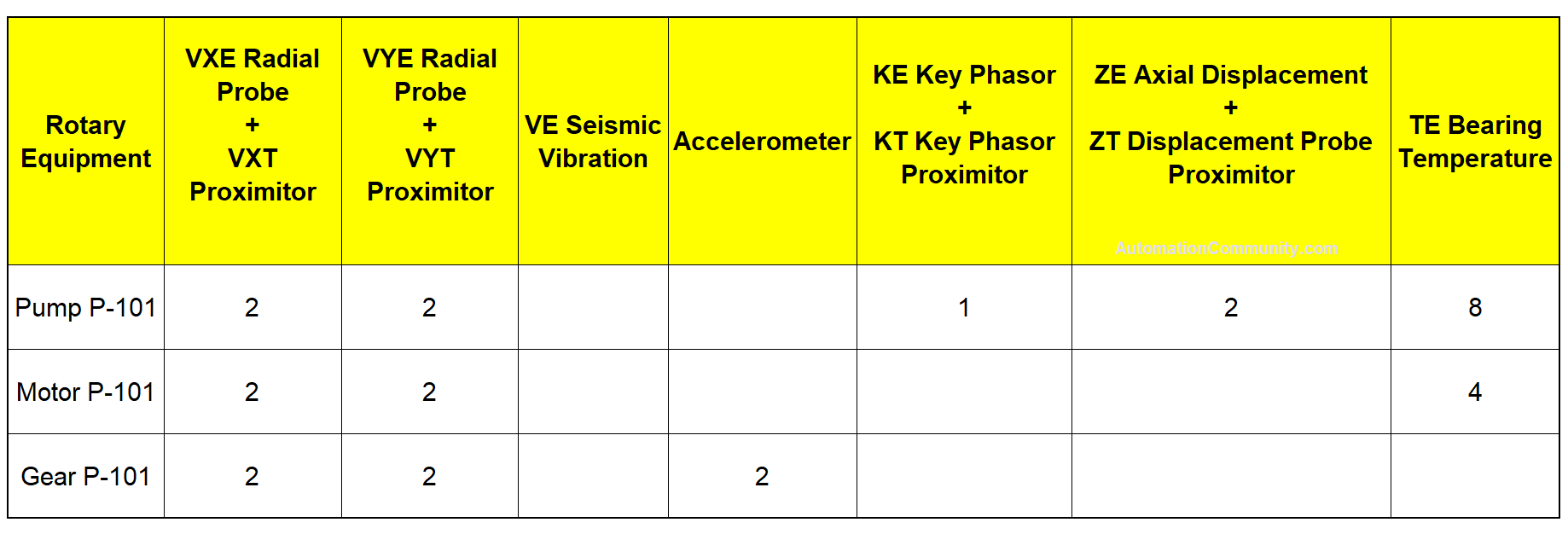
Sample I/O List
Scope of Work
The scope of supply and work for the MMS system should cover at least the following aspects.
- Project management, execution
- Applicable Code / Standard (e.g. API 670, API 612, IEC 61508, IEC 61511, IEC 62443)
- Specification for MMS &/ CMS
- System Design (System Architecture) and interfaces
- Network design
- IT / OT / Wireless integration
- Hardware configuration,
- SIL and Cybersecurity requirements
- System configuration, parameter setting, relay logic
- FAT, iFAT
- SAT
- Drawing and documentation
- Calibration, Inspection, and testing reports
- Training
Sample Key Components of MMS System
The blow table shows sample details of the Bently Nevada vibration monitoring system.
| Bentley Nevada | 3500 |
| Power supply | 3500/15 (Dual Power Supply) |
| Keyphasor Module | 3500 2-Ch : 3500/25-01-01-CC |
| Proximitor/Seism Monitor | 3500 4-Ch : 3500/42-09-01 (SIL) |
| Transient Data Interface (TDI) Module | 3500/22 |
| Temperature Monitor | 3500 6-Ch : 3500/61-01-01 (SIL) 3500 16-Ch : 3500/65 (Non SIL) |
| Relay Module | 3500 4-Ch: 3500/32-01-BB (SIL) |
| Communication Gateway (Ethernet /RS485) | 3500/92-04-01-01 |
| LCD Display | 3500/93 (B&W) 3500/94 (Color) |
You can download the Bently Nevada 3500 Machinery Condition Monitoring System datasheet. Get Your Files.
Design of Machine Monitoring System (MMS)
Points to be taken care of during the design of the MMS system.
Allowed maximum cable length between transducer and monitor. A low-capacitance instrument cable is desirable.
E.g. Standard maximum cable run for Bentley Nevada transducers is recommended as 305 meters. For extended field wiring, capacitance limits for hazardous areas and frequency response degradation are required to be evaluated for suitable low cable capacitance cable selection.
Bentley Nevada prefers cable capacitance of ~ 100pf/meter for triad cable. Generally, the Instrument cable vendor can offer to reduce cable capacitance up to 175 pf/meter capacitance by increasing the thickness of cable insulation (XLPE).
Bentley Nevada “Application note” on extended field wiring can be referred to verify total machine monitoring loop capacitance limits if any.
See application notes on this topic by the reputed supplier. Download Now.
Relay sizing (counts) – Critical signals shall be hardwired from the machine monitoring system to ESD/DCS for taking necessary trip actions. Pre-alarm signals should be considered via the serial interface.
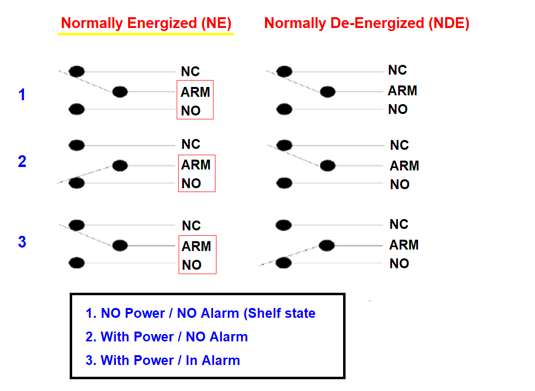
Relay contact wiring is important. Ideally, the Machine should not operate without an MMS system. That means that when MMS is not power-on, it will not allow machine operation.
In such case, relay shelf state (no power) C-NO of Normally Energized relay wiring may be used. Once powered the system, this C-NO contact will change to make condition under no alarm condition so it will pass healthy status.
MMS I/O count and GA drawing of sensor, probes, and proximiters with the part number and dimensions from the rotary equipment supplier should be sent to the MMS vendor for compatibility verification. Configuration details like type of value (RMS or pk-pk ) for vibration sensors/accelerometer & frequency filter values (high pass & low pass) should be available
Based on asset classification/ availability requirement machine condition /monitoring system can be specified as simplex hardware, redundant CPU, redundant power supply, redundant sensors, and/or condition monitoring requirements like root cause diagnostic and thermodynamic performance monitoring.
In general MMS (3500 racks) to CMS (system 1) connection is not redundant but simplex. Location /distance between MMS rack and system 1 to be known for the selection of module (e.g. Fiber optic based ethernet module TDI can be selected for longer distance)
Normally 3500/42 module is used for radial vibration, acceleration (casing vibration), and axial displacement. This module comes with 4 channels (1,2,3,4). The configuration of these modules shall be done in such a way that Channel 1,2 monitoring shall be of the same type and Channel 3,4 shall be of the same type. Axial displacement in channel 1, Radial vibration in channel 2 is not possible.
Earthing module ( 3500/04) may be required when external barriers are not applicable.
Further Reading!
There are two types of maintenance. Reactive Maintenance and Proactive Maintenance. One cannot have a predictive Maintenance System without using Condition Monitoring techniques.
Predictive Maintenance uses condition monitoring for the collection, comparison, and storage of measurements that define a machine’s health by monitoring displacement, velocity, acceleration, etc.
Although Predictive Maintenance can certainly be considered as the backbone of a Proactive Maintenance system. However, it does not necessarily guarantee that the root causes of problems or failures will be eliminated, or even addressed.
Bentley System 1 provides continuous condition monitoring information for use in a proactive maintenance program.
Preventive and Predictive Maintenance systems should focus on developing a strategy on how to deal with all the reasons why things go wrong so as to pinpoint the root causes and eliminate them.
Predictive Maintenance reduces repair costs by having early warning signs, reduces the number of unnecessary inspections, eliminates catastrophic failure costs, reduces unscheduled downtime, and increases machinery reliability.
This article was published in the Automation Community Competition.
Read Next: