In this article, you will learn how to do Modbus communication between the Mitsubishi PLC HMI PID controller with RTD to measure temperature.
Project Details
Consider the following example.
A heater is used in a system to raise the temperature of the liquid that has been added to a vessel depending on various set points. The heater must work in three stages during the course of a cycle.
When a cycle start button is pressed, the heater is activated in the initial stage. The heater is turned off for p seconds after the temperature of x° C has been reached. During this time, the liquid’s temperature drops.
The heater is restarted when p seconds have passed and kept running until the liquid reaches y° C. The cycle is completed when the heater is turned back on after the liquid has cooled for q seconds and reaches z° C. The next cycle won’t begin until the liquid temperature drops below x° C.
The variables set from the HMI are x, y, z, p, and q.
The Process value (Running temperature) of the liquid contained in the vessel is required by PLC in order to complete the process.
Two of the possible methods by which the aforementioned may be accomplished are as follows:
It is necessary to use a temperature transmitter that offers 0-10v/4-20mA/0-20mA in addition to RTDs or thermocouples. The analog input module of the PLC receives this voltage or current output signal, which provides the process value (running temperature) of the liquid.
In addition to these, HMI is a must requirement for altering x, y, z, p, and q.
A PID controller with a communication option is required in addition to the RTD or thermocouple. Using the Device transfer function in GT Designer 3, the Process value of the liquid’s temperature obtained at the PID end is transmitted to the PLC via HMI on the RS485 protocol.
PID is therefore needed for the second technique, whereas the first method requires a transmitter and an analog input module in addition to a PLC and an HMI.
If only cost matters, the second method is cheaper than the first one. So, in this case, the process is carried out using the second way.
Details of the controller and devices used in this case are as follows:
| PLC | HMI | PID Controller |
| Mitsubishi FX3U | Mitsubishi GS2107 | Selec PID500 |
The steps for executing the process are as follows:
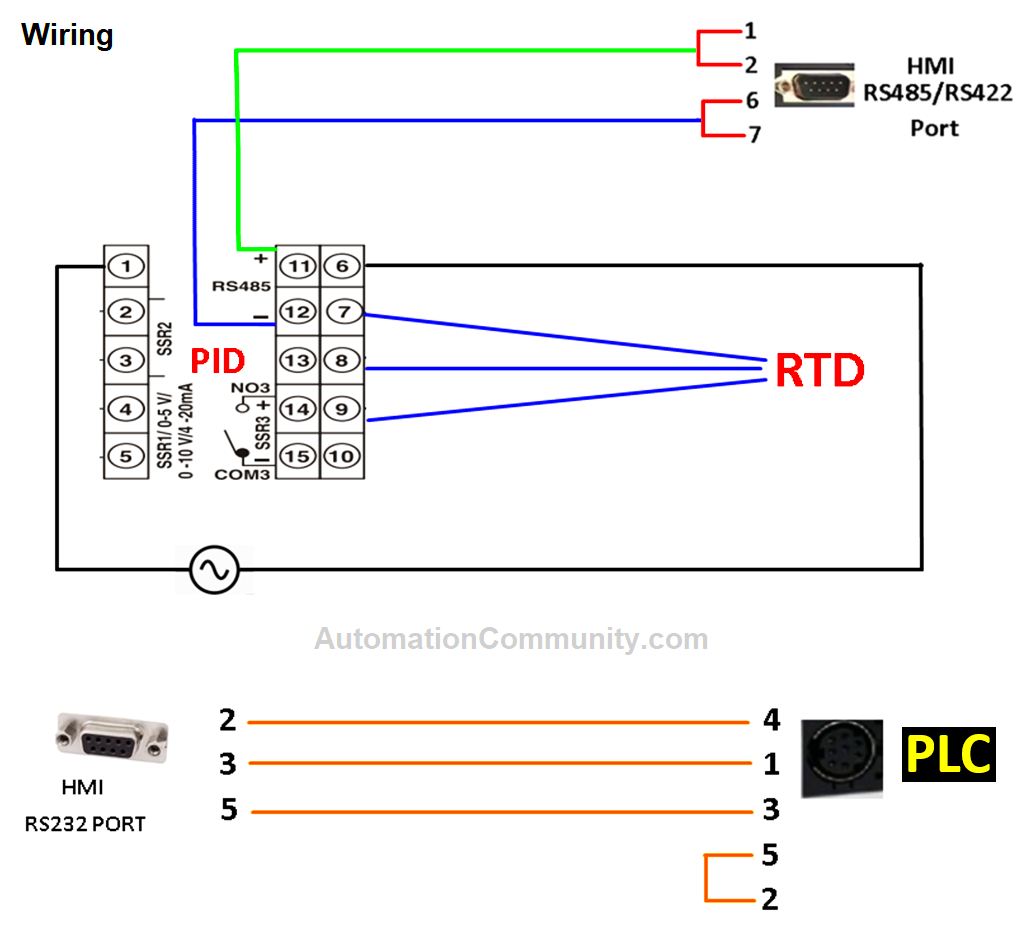
- Wiring the RTD/Thermocouple to PID Controller, Connecting the PID controller to HMI using RS485 cable, and Connecting PLC to HMI using RS232 cable.
- Writing the logic in GX works2(PLC software), assigning data registers for x, y, z, p, and q.
- Communication-related PID controller parameterization.
- Using the GT Designer 3 software to set up an HMI with both PID and PLC on two distinct channels.
Mitsubishi PLC HMI Configuration
Take a look at the schematic and connection details below.
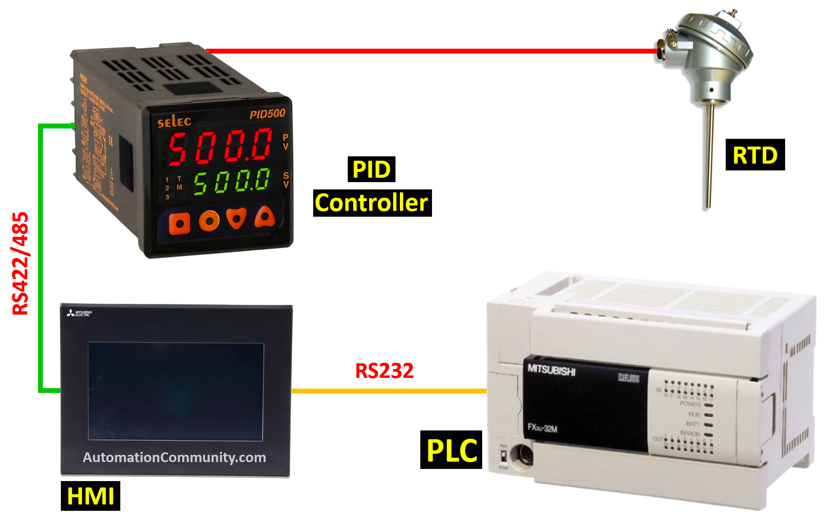
The following image shows the wiring between PLC, HMI, PID Controllers, and RTD.
Wiring between PLC HMI PID Controller
PLC Logic
The below table lists the main I/O of the PLC program.
| Device Name | Comment |
| M0 | Sys on |
| X000 | Start |
| Y000 | Heater |
| D0 | Final PV |
| D2 | x° C |
| D4 | y° C |
| D6 | z° C |
| D30 | p seconds |
| D32 | q seconds |
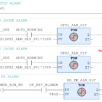
Rung 1
From HMI “p” and “q” seconds are defined in D30 & D32, the values of which are multiplied by 10(dec) and stored in D20 & D22 to define the Set values of hundred milliseconds timers T0 and T1 in Rung 5 and 7.
Rung 2
When pressing the start button X0, the system will only start through M0 if the conditions listed below are met.
- Liquid’s temperature (value of D0) is below x° C
- x° C < y° C < z° C as defined from HMI
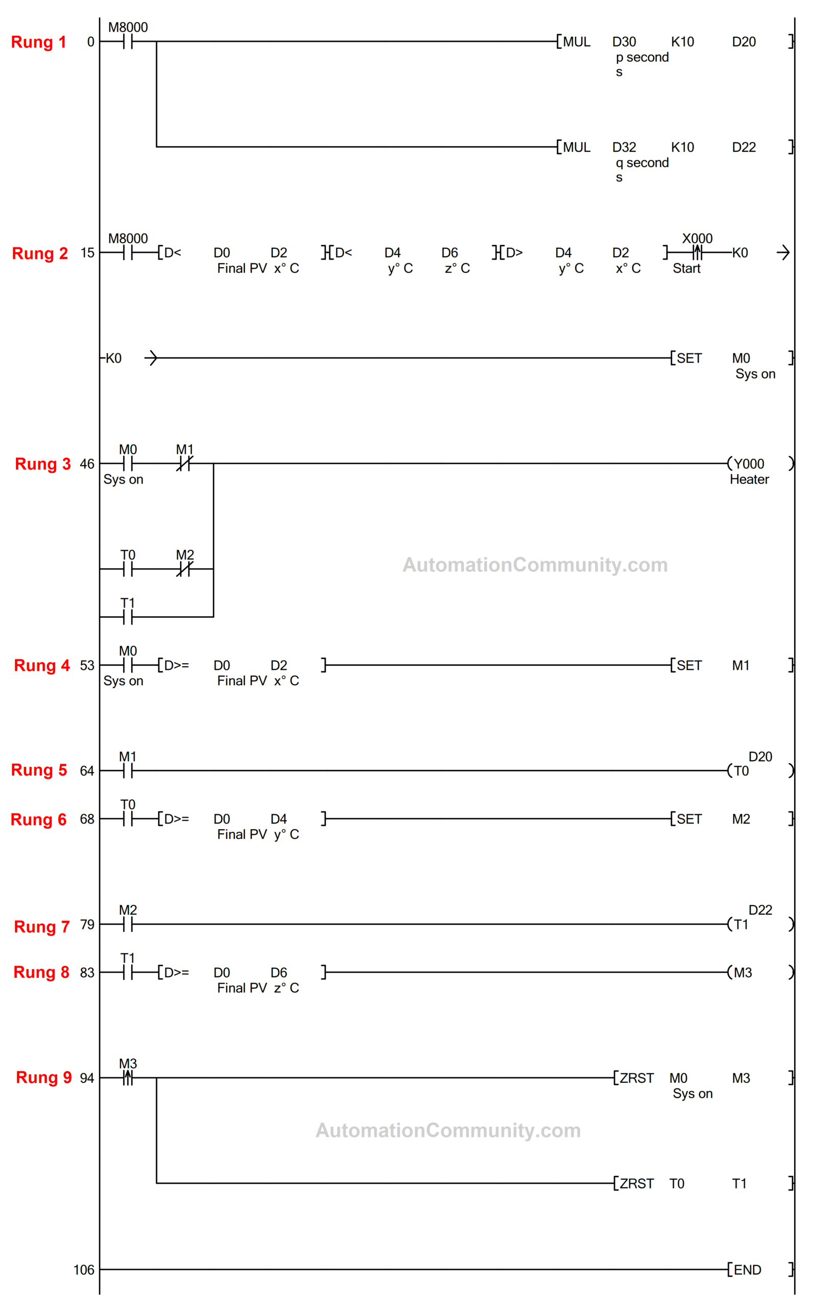
Rung 3 & 4
When the start button X0 is pressed and all the prerequisites from the preceding rung have been satisfied, the heater is turned on through M0 until the temperature reaches x° C.
M1 shuts off the heating source when x° C is reached.
Rung 5 & 6
The timer begins counting after the heater’s supply is shut off. After the completion of this time, the heater is again turned on through the parallel branch in Rung 3.
The heater supply is then turned off as soon as the liquid reaches a temperature of y° C since M2 is high.
Rung 7, 8, & 9
Soon as the supply of the heater is shut off, the timer starts counting q seconds. Once the q seconds have passed, the heater is again turned on through the second parallel branch in Rung 3.
The heating supply is turned off as soon as the liquid reaches z° C since M3 is high. As soon as the M3 actuates, all timers and memory bits are reset to finish the cycle.
PID Controller Parameters
Below are the default PID Communication parameters
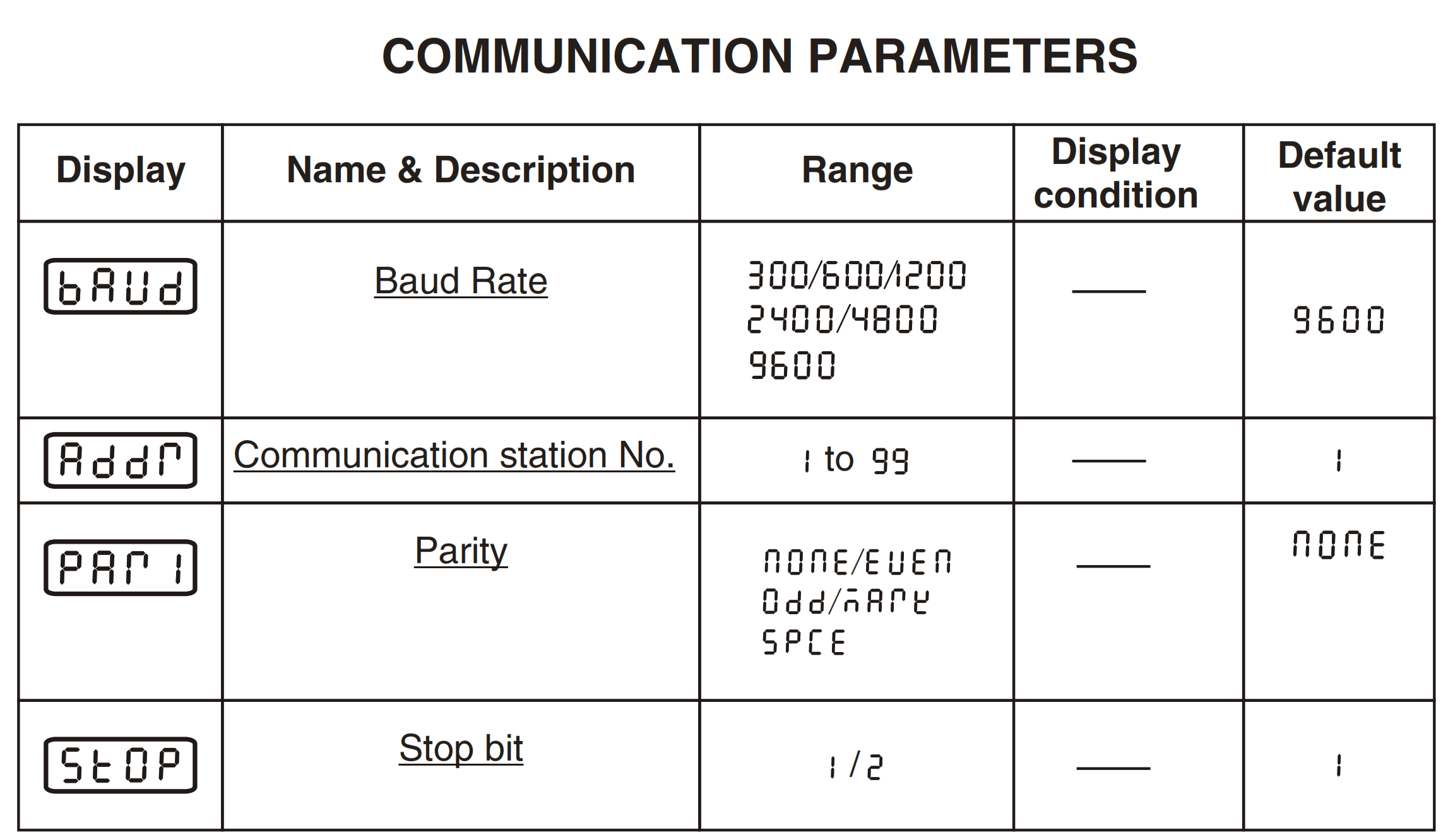
Define Communication station No. as 2 and set the Stop bit to 2.
Use Baud Rate and Parity default values.
The parameter settings in the HMI should be the same as above except for the station address.
Since PID and HMI are communicated using RS485 protocol, the Modbus address of process value is required in order to obtain it at the HMI end.
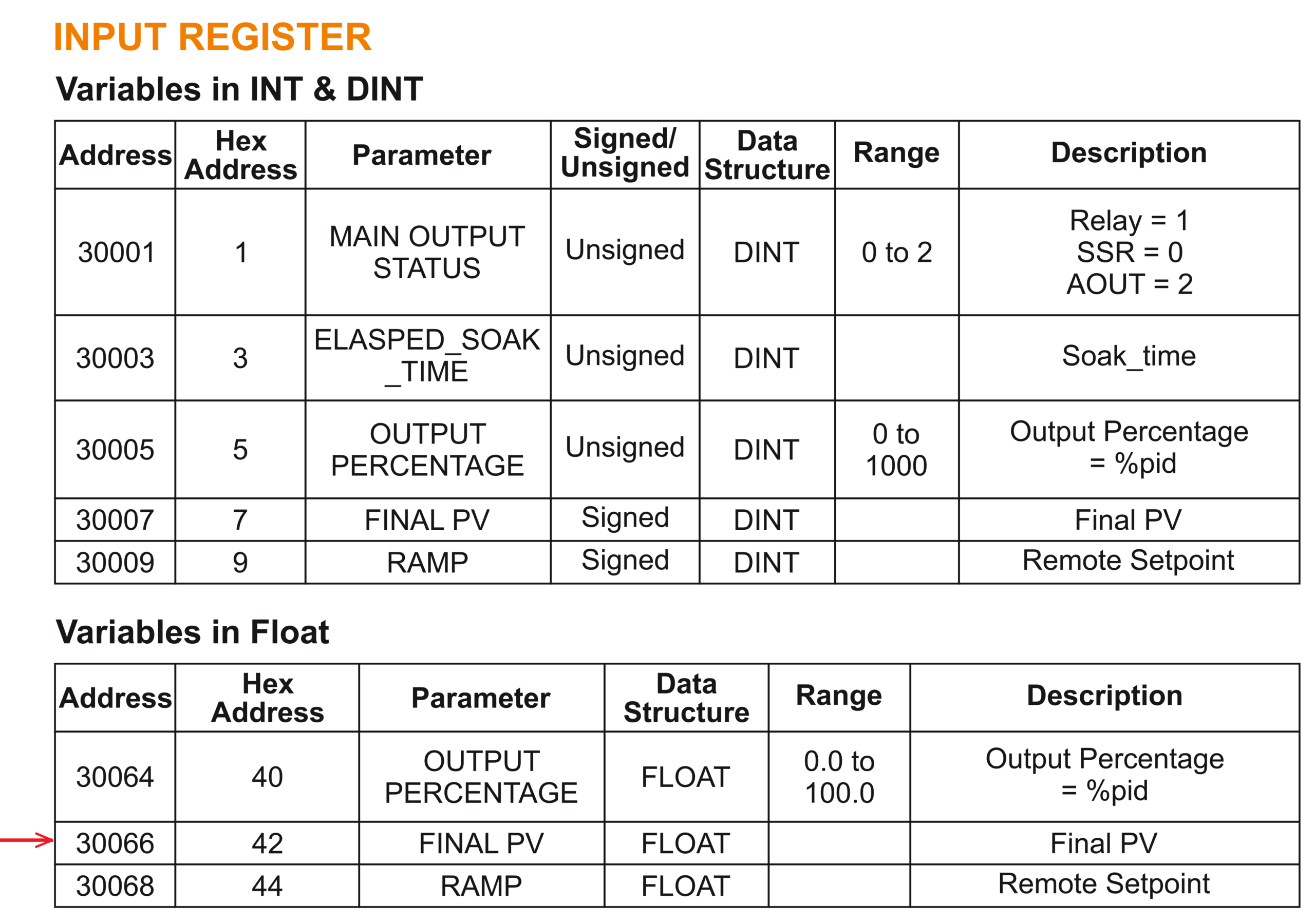
30066 reads the Process value (Running temperature) of any liquid contained in a vessel having the Resistance Temperature Detector as the temperature-sensing device.
Mitsubishi HMI Programming
Here we are using MELSOFT GT Designer 3 Mitsubishi Software and described the HMI programming in brief steps as follows.
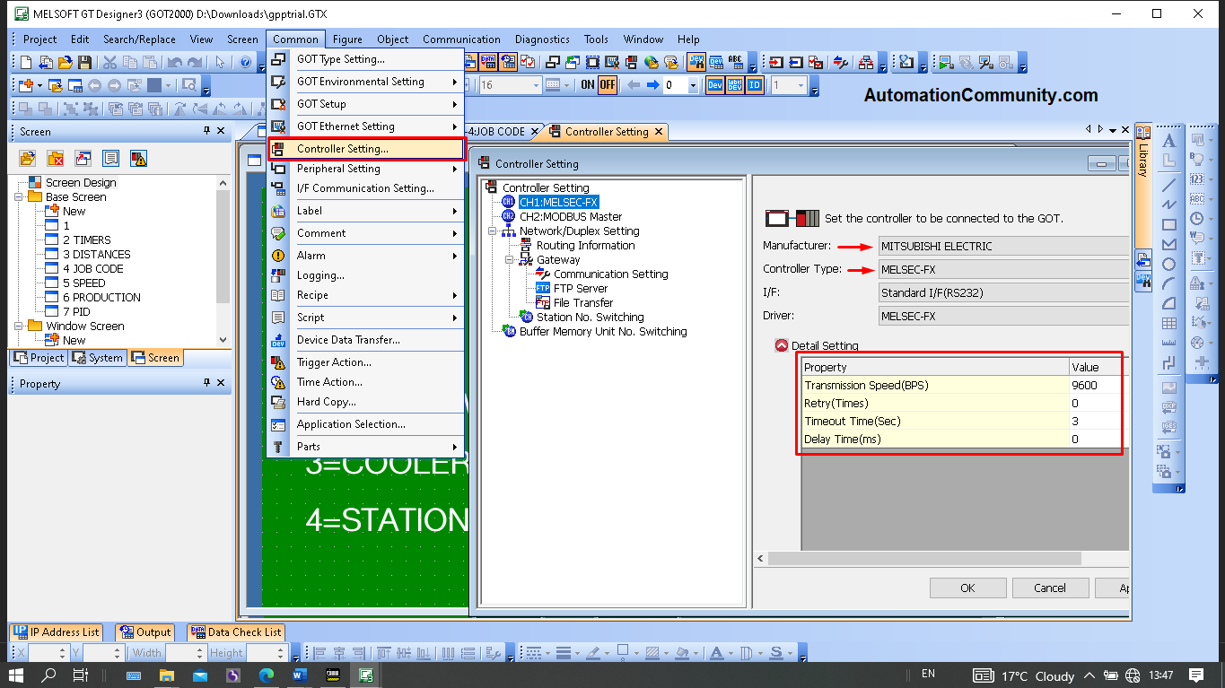
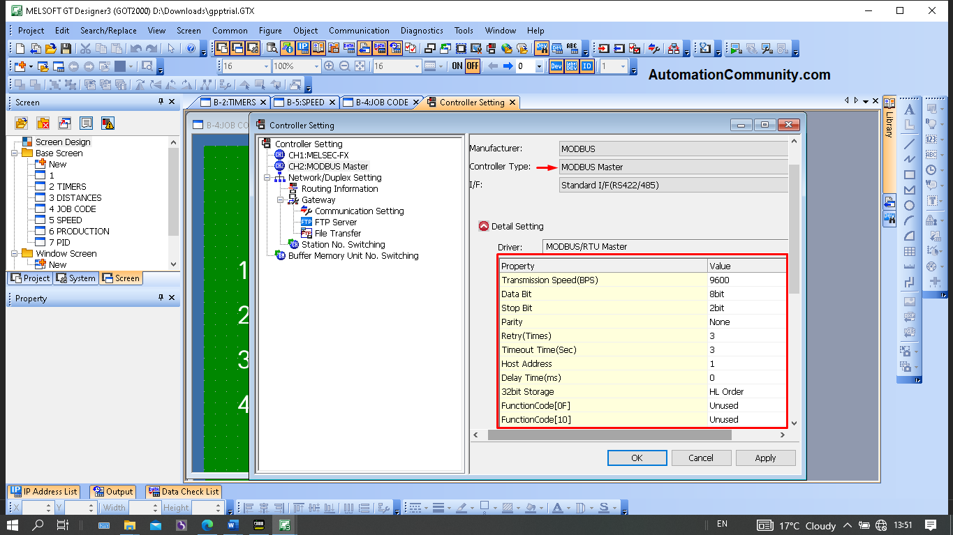
Assign Channel 2 as Modbus Master on the RS485 interface and Channel 1 controller as MELSEC-FX on the RS232 interface in the controller settings with the highlighted settings.
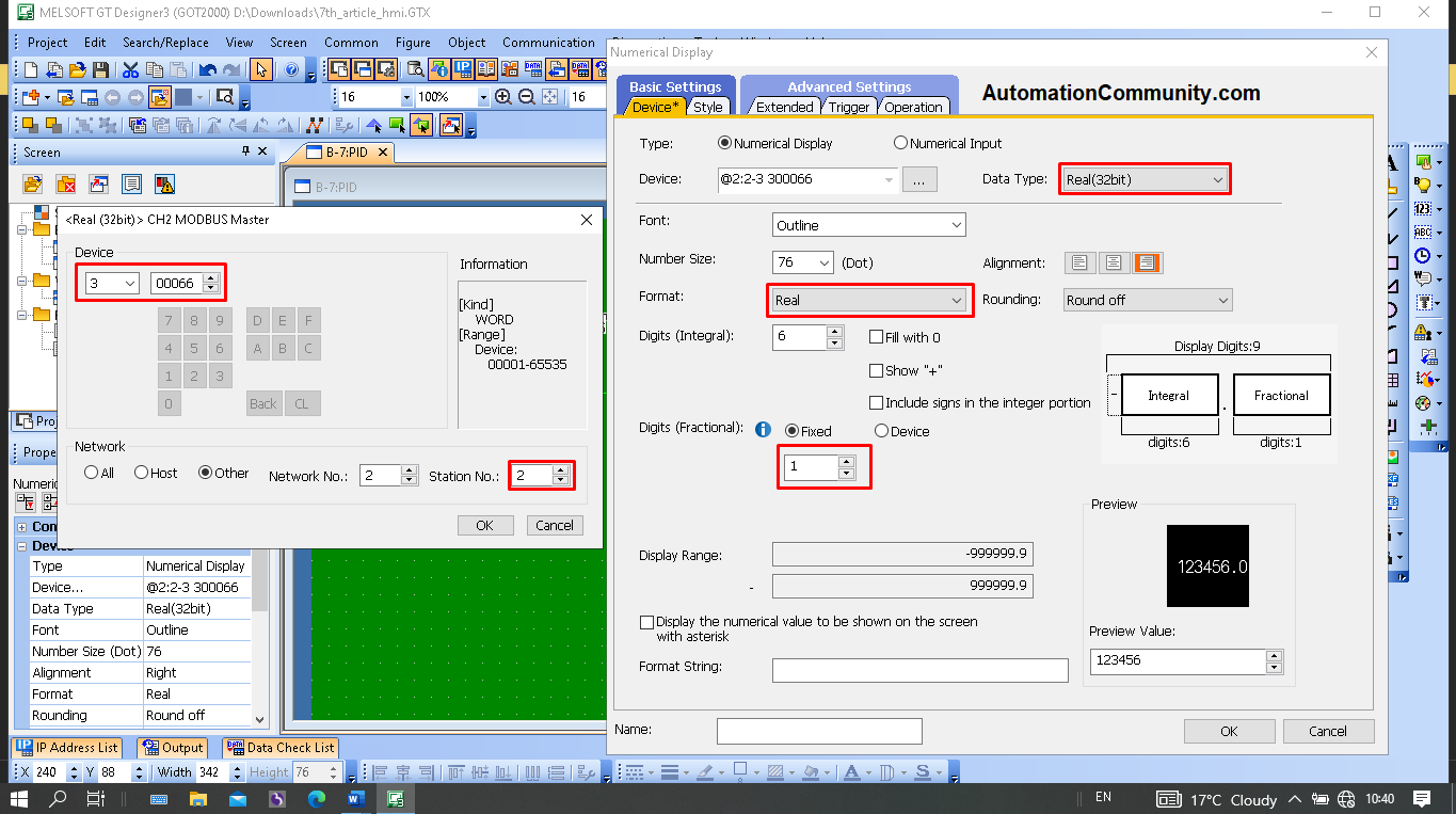
To show the Process value (Final PV) obtained from PID, tag the “Numeric Display” element as below.
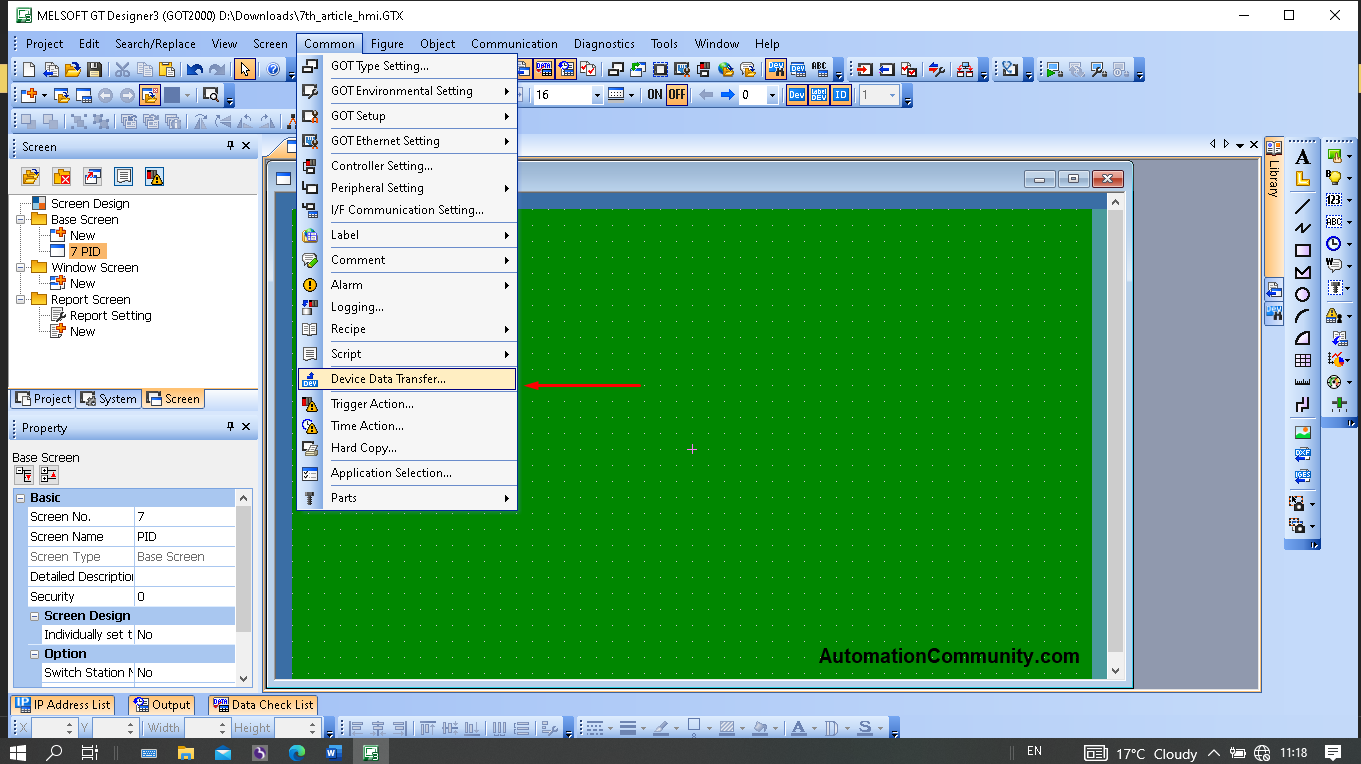
Transfer this process value to the PLC using the Device transfer function
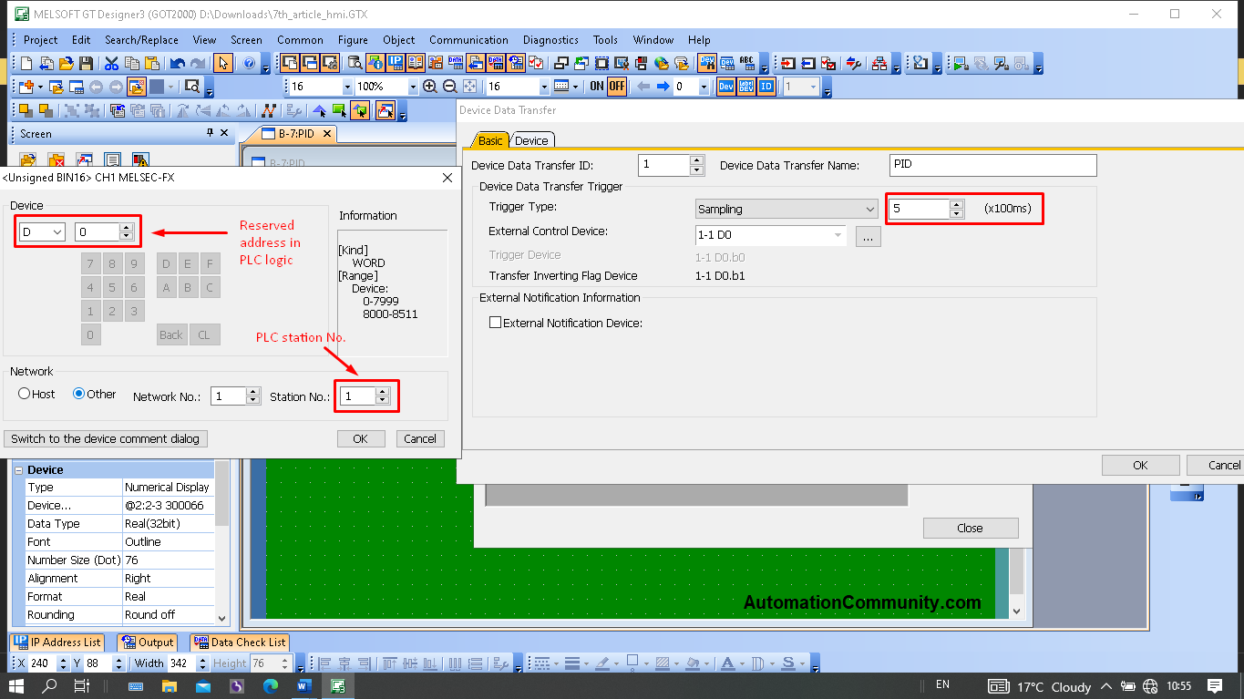
In the basic configuration of the “Device Data Transfer” function, tag the device address as D0 assigned for Process value in PLC (See PLC logic). Station number 1 ensures that the tag is of PLC.
To ensure that the Data read from PID is transferred once every 500ms, set the transfer rate to 500ms.
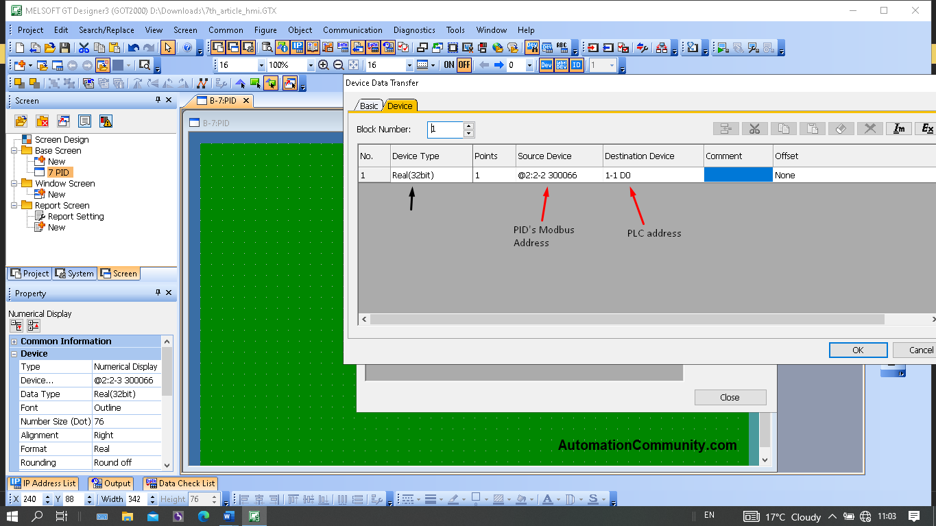
Define the Source device as Modbus Master (Station number 2) with the address 300066 in the Device configuration of the “Device Data Transfer” function.
Set the MELSEC-FX (Station 1) device as the destination device, and set the address to D0.
Make sure “Real” is selected as the Device type. As a result, data is read from the PID and sent to the PLC every 500ms.
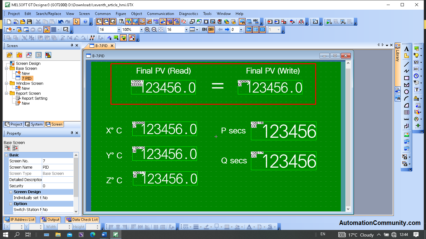
Apart from these, take the Numeric inputs and tag them as per PLC logic.
- D2 (Real) for x° C
- D4 (Real) for y° C
- D6 (Real) for z° C
- D30 (Int) for p secs
- D32 (Int) for q secs
On the final screen below, temperature (Final PV), which was read from PID and written to PLC, is also highlighted.
Conclusion
Modbus Communication between Mitsubishi HMI and PID controller (PID500) is demonstrated with the help of a Liquid processing example.
Read Next:

Suresh
April 5, 2023Thank you for the information