In this article, you will learn the PLC programming for Poka-Yoke assembly table and its importance for the production line.
When assembling small parts to create a large assembled product, workers use an assembly table.
The operator may select or use the incorrect part during gauge measuring or assembly of a product. This we call human error.
Poka-Yoke Assembly Table
When an operator is new to operating an assembly line and a faster assembly rate is required to meet a target, the likelihood of error rises.
To make the assemblies mistake-proof, a Poka-Yoke is introduced using PLC and HMI.
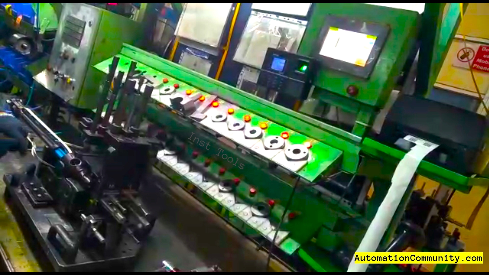
When an assembly model is chosen in HMI and the cycle is initiated, HMI displays a picture of the component or instrument that the operator will pick up next.
An additional lamp blinks at the component slot in addition to the display. The buzzer will sound and the HMI panel will indicate “wrong selection” if the operator picks the incorrect instrument or component.
The cycle is reset for the next cycle after the last piece of equipment is picked and placed.
A Short Explanation of the Process
All of the six gauge components, two screw guns, and two color markers are positioned in their slots such that their sensing sensors have already been activated and are providing inputs to the PLC in the form of pulses.
If any slot’s part is missing at the beginning of the cycle, a buzzer will sound and the text “Part missing” will appear on the HMI screen.
Once the final part has been picked up and repositioned, the cycle will be complete. At this point, the cycle begins anew.
A sample video is shown below for the Poka-Yoke assembly table.
List of Inputs and Outputs
The list of Inputs and Outputs is as below:
| PLC Address | I/O | Remarks |
| 0.06 | Input | Part 1 |
| 0.07 | Input | Part 2 |
| 0.08 | Input | Part 3 |
| 0.09 | Input | Part 4 |
| 0.10 | Input | Part 5 |
| 0.11 | Input | Part 6 |
| 1.00 | Input | Clamp/Unclamp PB |
| 1.08 | Input | Green Marker |
| 1.09 | Input | White Marker |
| 0.00 | Input | M6 Screw Gun |
| 0.01 | Input | M8 Screw Gun |
| 100.0 | Output | Clamping Valve |
| 100.1 | Output | Lamp Part 1 |
| 100.2 | Output | Lamp Part 2 |
| 100.3 | Output | Lamp Part 3 |
| 100.4 | Output | Lamp Part 4 |
| 100.5 | Output | Lamp Part 5 |
| 100.6 | Output | Lamp Part 6 |
| 100.7 | Output | Buzzer |
PLC Programming for Poka-Yoke
One model’s logic is written. On the basis of the following logic, more models can also be interlocked.
Rung 1
If the 15.00 signal is not activated, the cycle has not begun. If a component is absent at the beginning of the process, the sensor for that component won’t produce a pulse, deactivating the PLC’s particular input or inputs.
As a result, 17.00 activates to display “Part Missing” on the HMI screen.
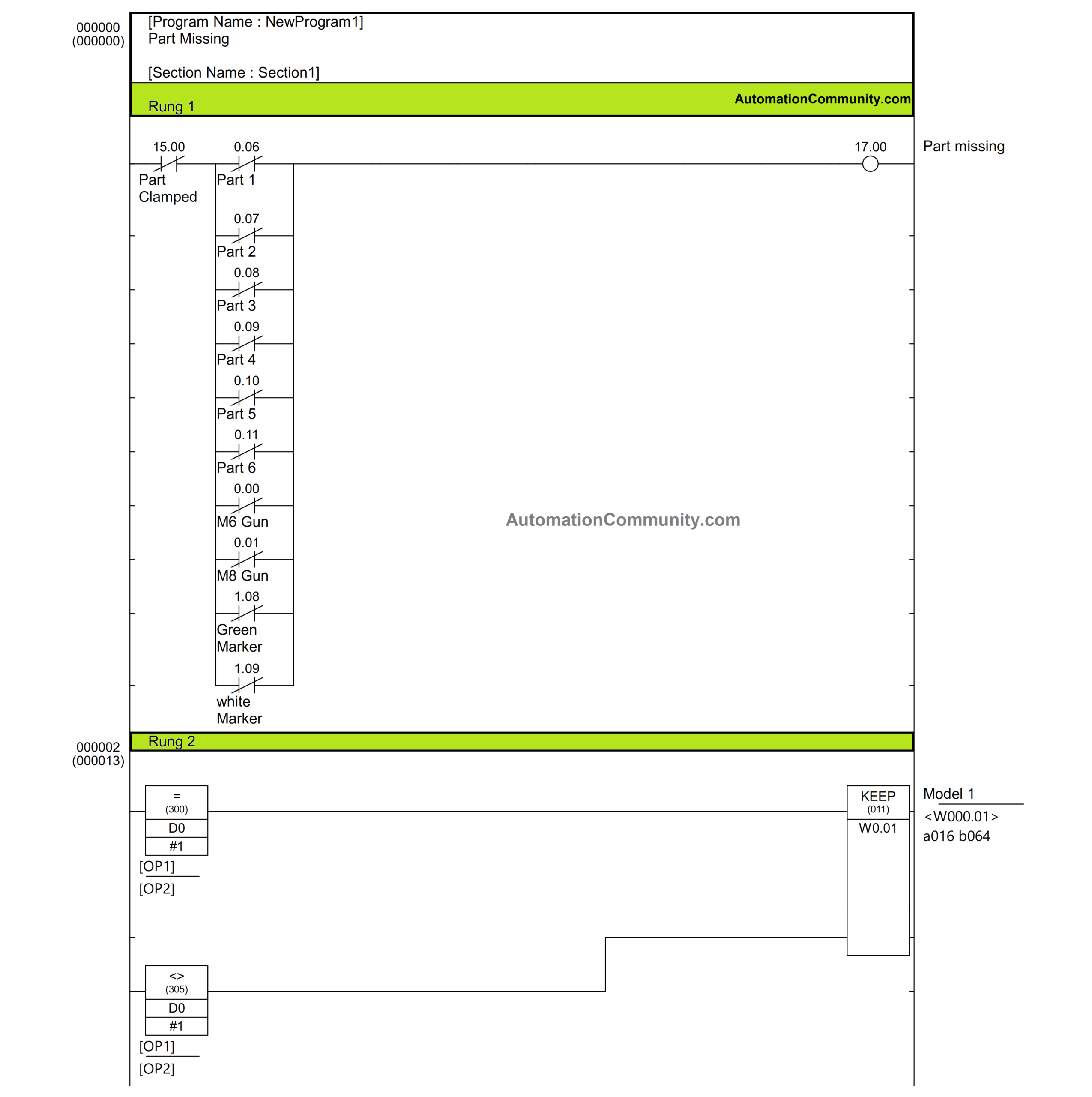
Rung 2
To choose the Model, use a D0-tagged number input on the HMI panel.
Considering that only one model is supported by the logic in this case, loading 1 will cause the bit “W0.01” to be set, allowing model 1 to be chosen. The bit “W0.01” is otherwise reset.
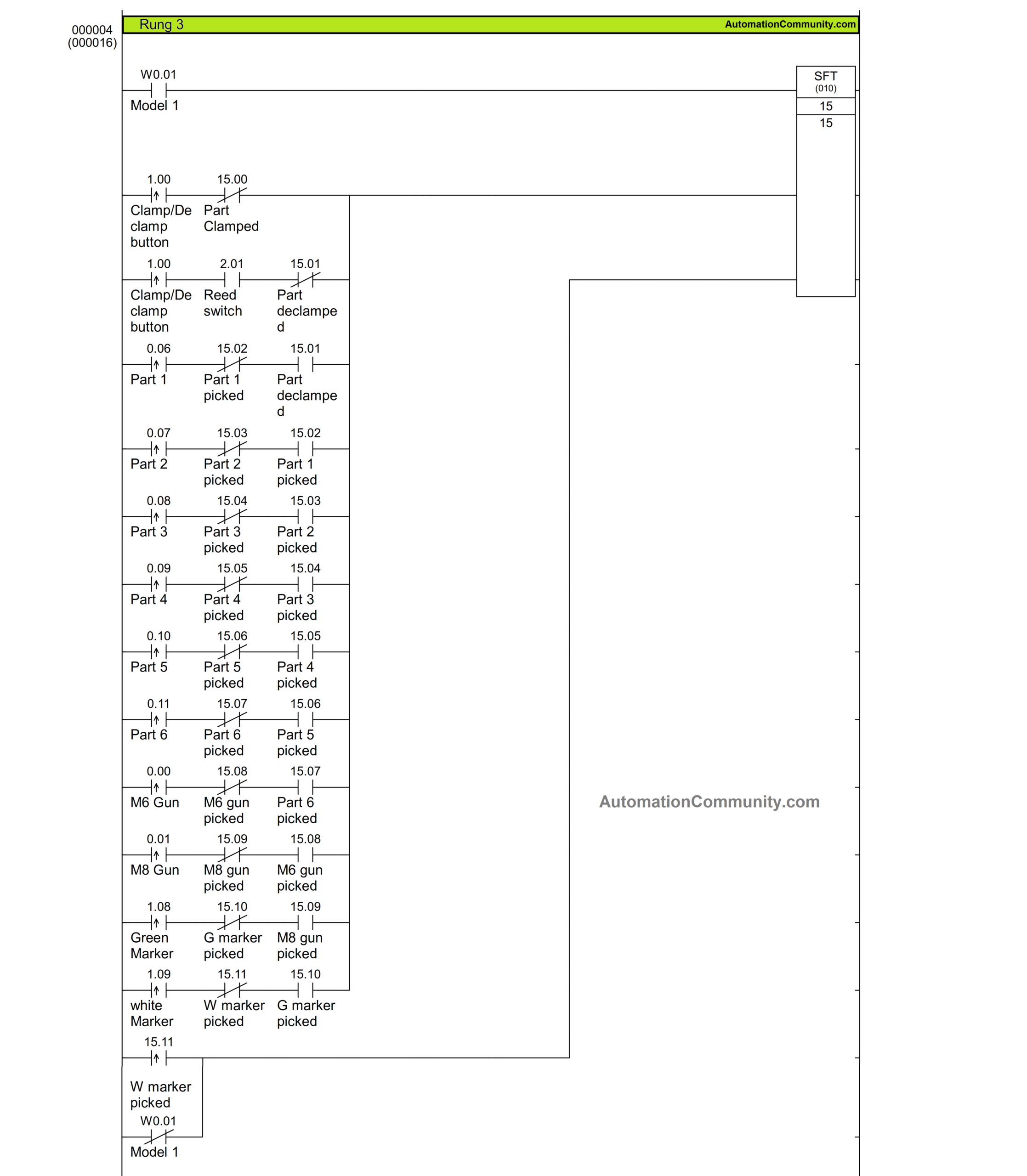
Rung 3
When employing the Shift Register instruction SFT, the Starting Word and End Word must be equal or less. 15 is fed here from both ends. Only when the data input is high, such as when W0.01 is high or Model 1 is selected, does the instruction run.
Consecutive bits are activated each time the Shift input is triggered. In this instance, the first triggering activates the 15.00, the second the 15.01, and so on until 15.15.
First, 15.00 is activated by pressing the Start push button, which also clamps the fixture assembly. After manual processing, the assembly is de-clamped by pressing the same button once more.
Once each of the six gauge measuring parts has been picked, two screw guns and two markers, the white marker being the final one are picked for processing. As the white marker is picked, 15.12 is activated. This 15.12 is used to reset the cycle by being the reset input for SFT instruction, or otherwise when Model 1 is not selected.
Each component or instrument input is interlocked so that it will only cause the bit to move when its turn to pick comes. When 15.12 is triggered, all the bits are reset.
Thus the series of the sequence is as follows:
- Clamp the fixture
- De-clamp the fixture
- Pick Part 1 to Part 6 in sequence one after the other
- Pick M6 Screw gun
- Pick M8 Screw Gun
- Pick Green Marker
- Pick White Marker
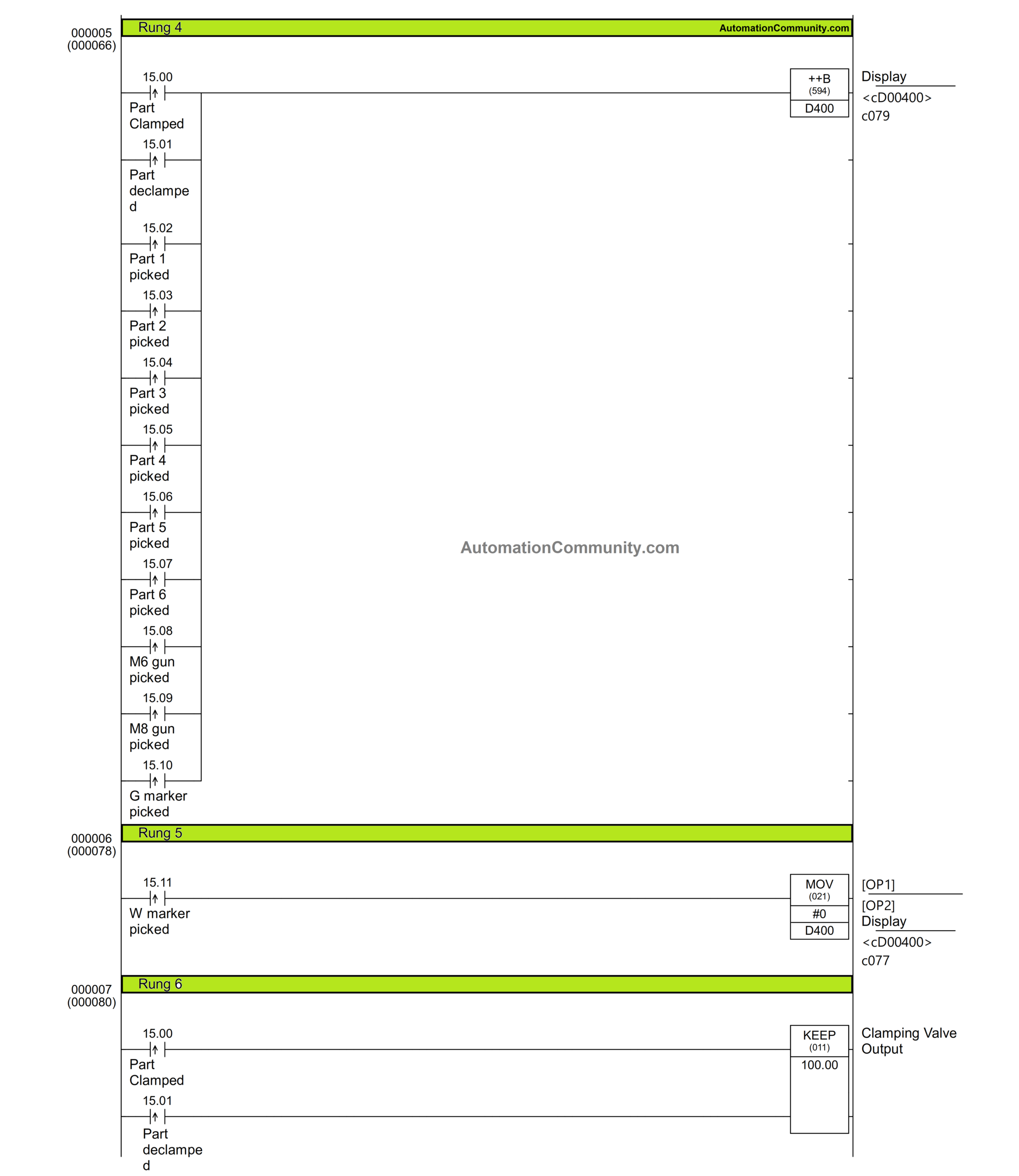
Rung 4
On the HMI screen, using this rung, a text of what to do next or a picture of what to pick next is displayed.
“Clamp” is shown at the beginning when D400 has zero value. This instructs the operator that the fixture should now be clamped.
When the fixture is clamped, D400 changes to have a value of 1. The word “De-clamp” is now shown, instructing the operator to unclamp the fixture. According to the order, a series of displays continues one after the other.
Rung 5
When the white marker is last picked up and relocated, zero is moved to D400 to display the “Clamp” text for the following cycle.
Rung 6
A pneumatic cylinder that is based on a single-acting valve that operates when 100.0 is set using the KEEP instruction when 15.00 is high is used to clamp the fixture.
When the push button is used to unclamp the fixture once more, it is reset. At this time, 15.01 actuates.
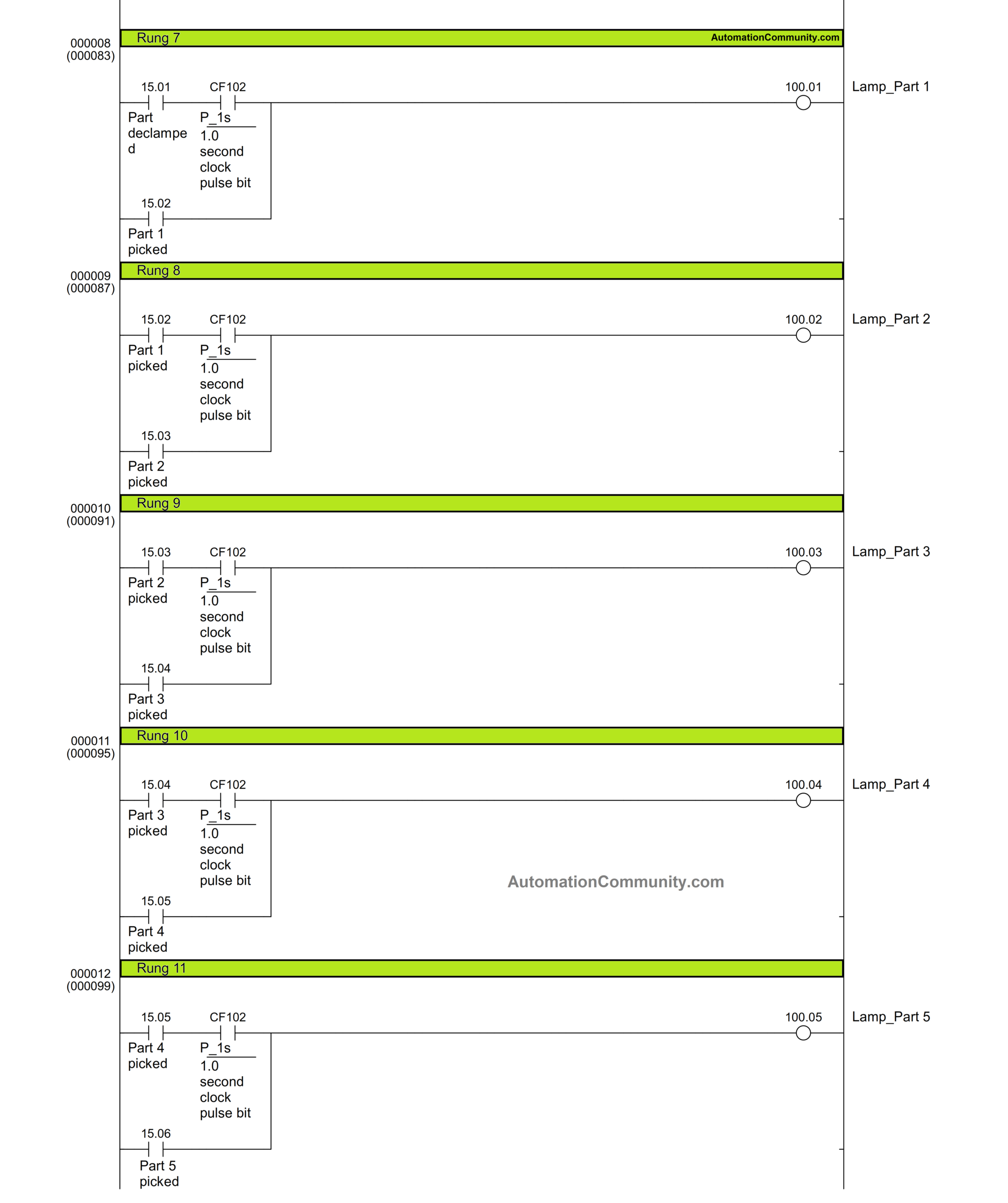
Rung 7 to 12
Each slot where the gauge pieces are placed has an indicator lamp set there. They blink till they are not picked and placed once.
The lamp is held on by the parallel actuating bit when the component is taken up and subsequently repositioned.
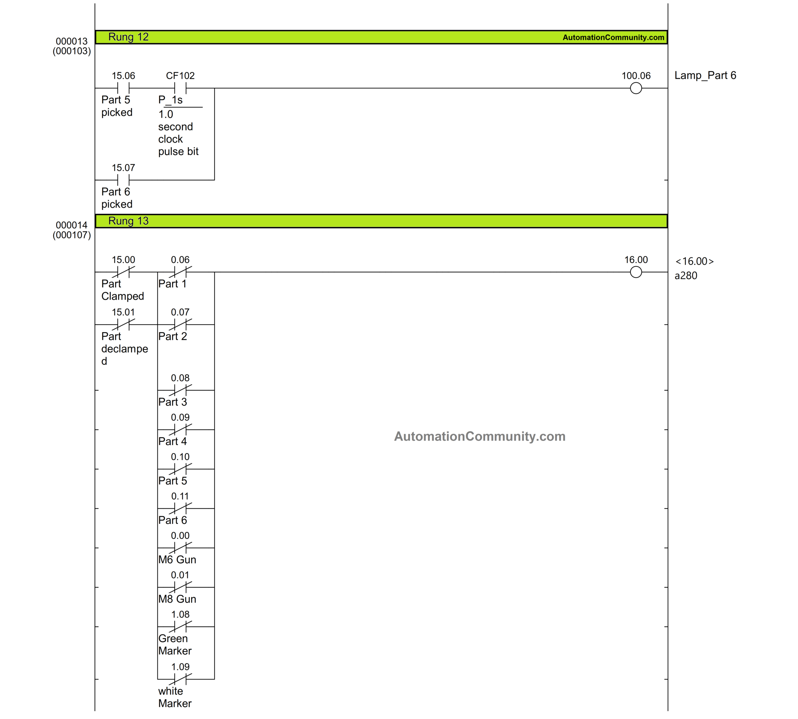
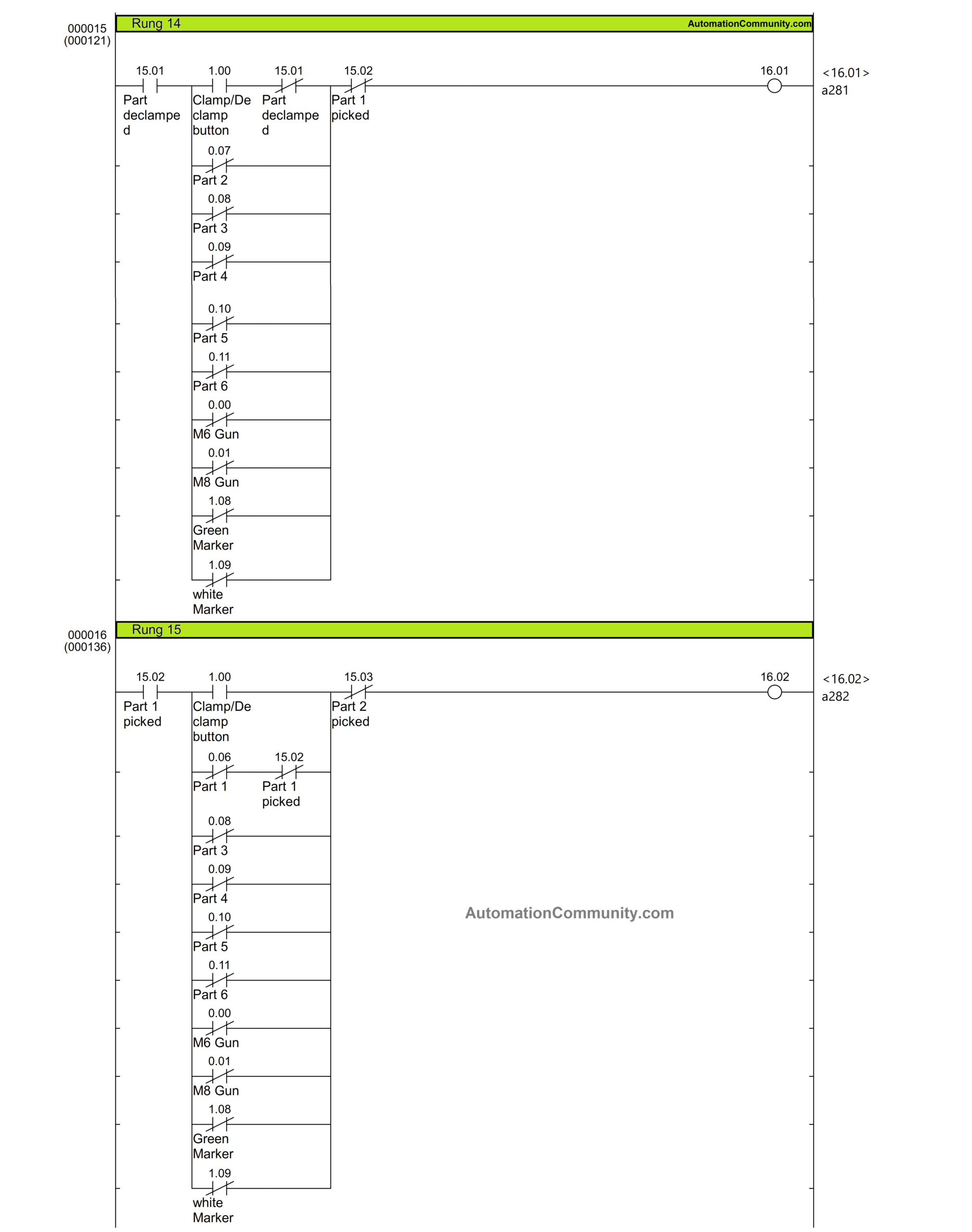
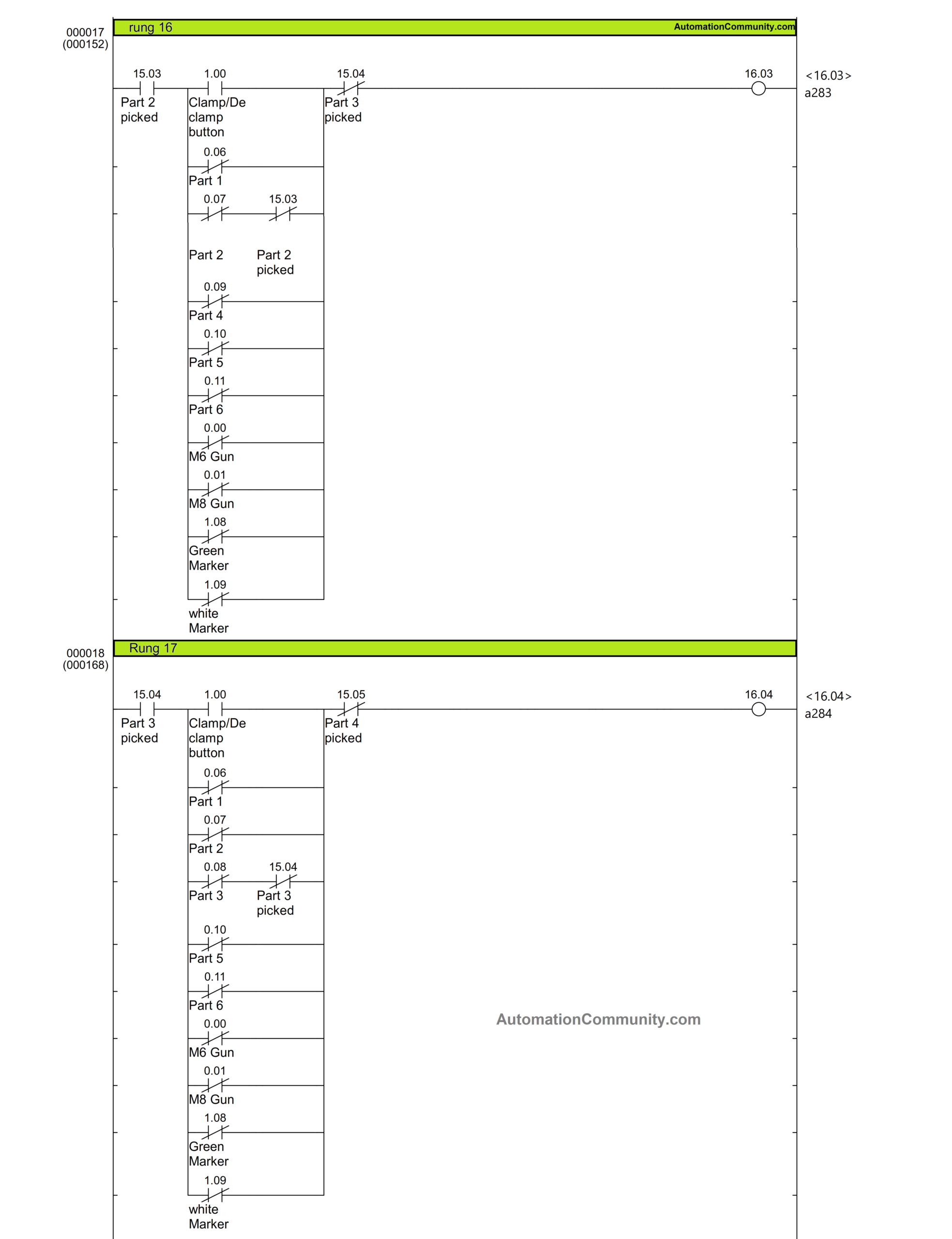
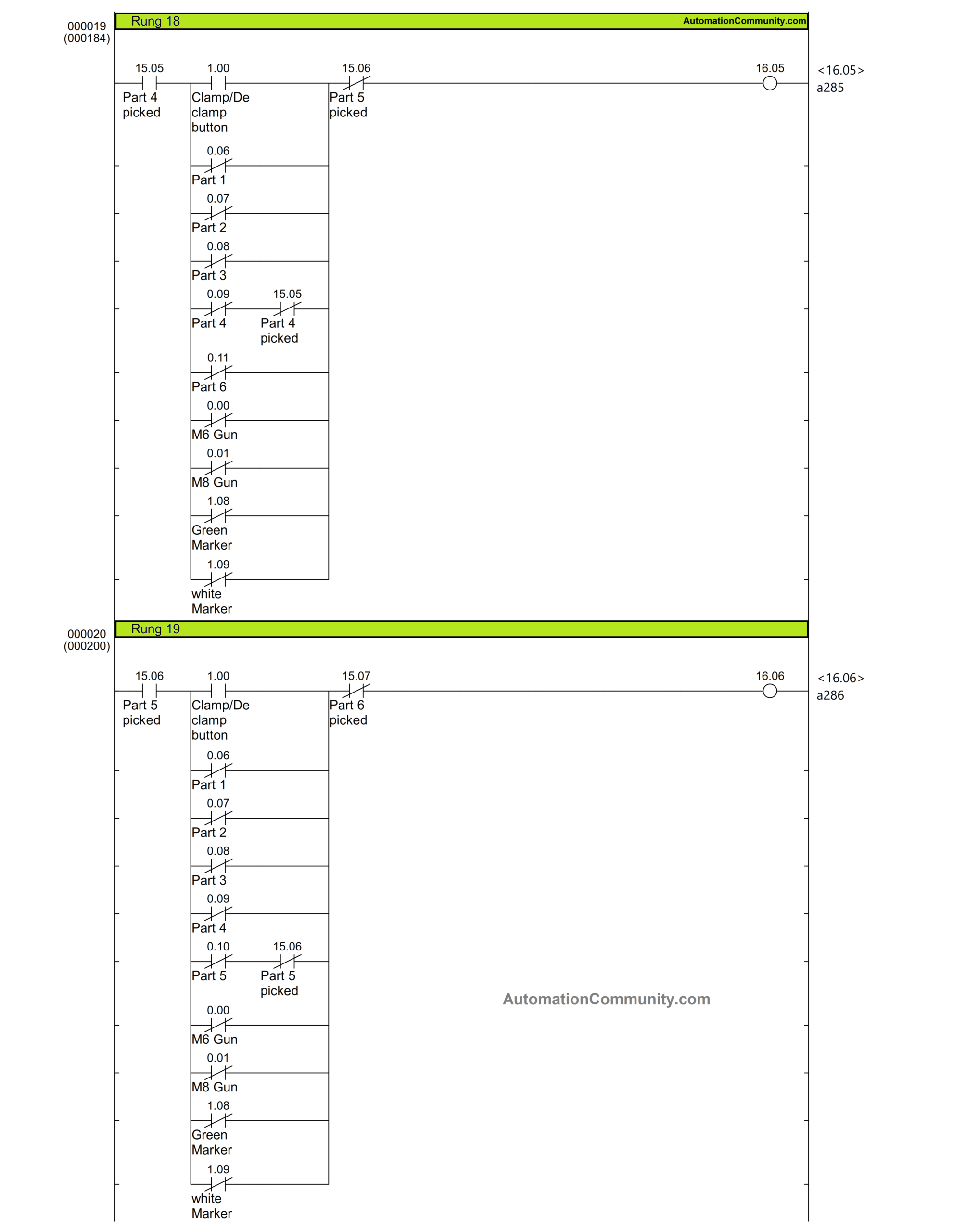
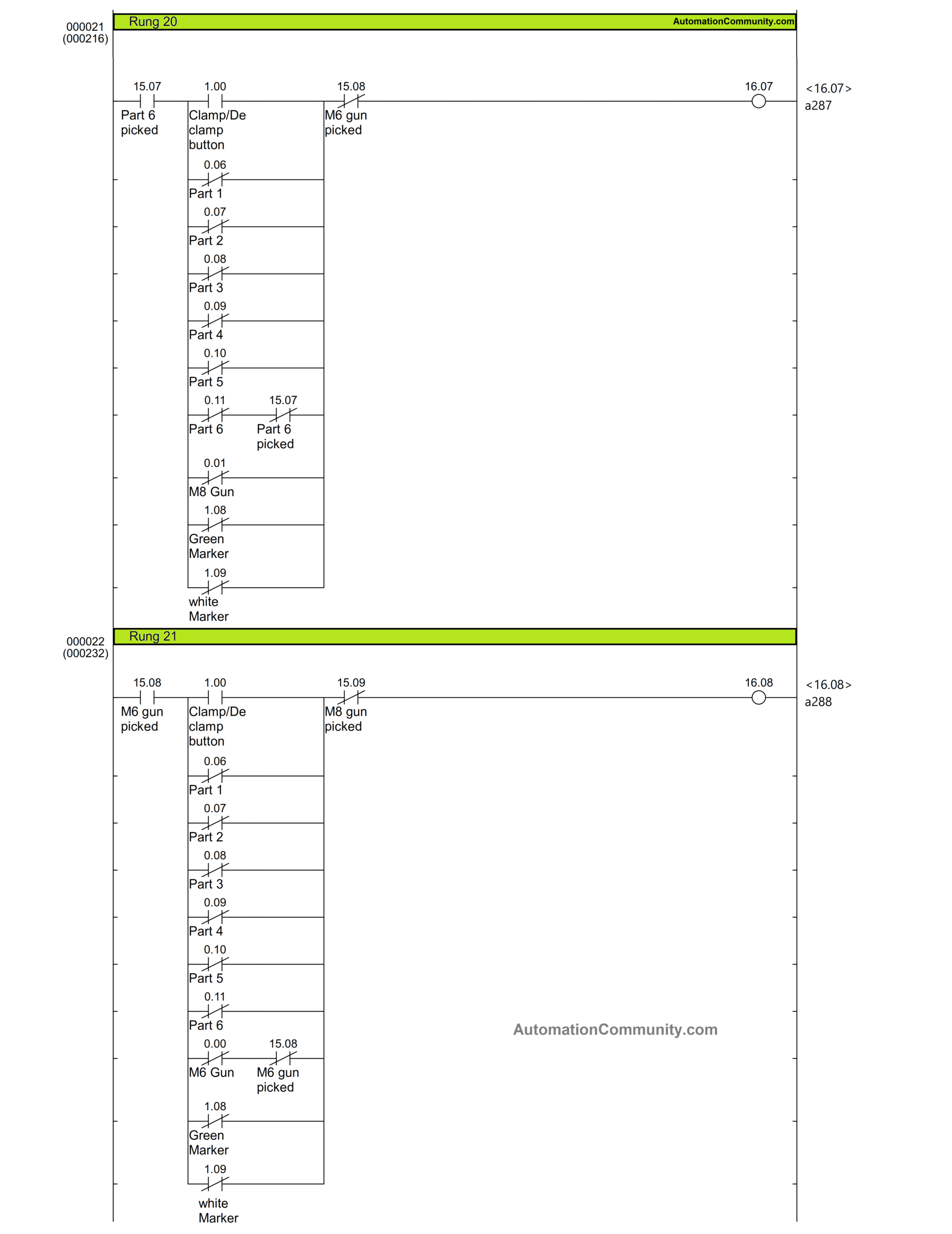
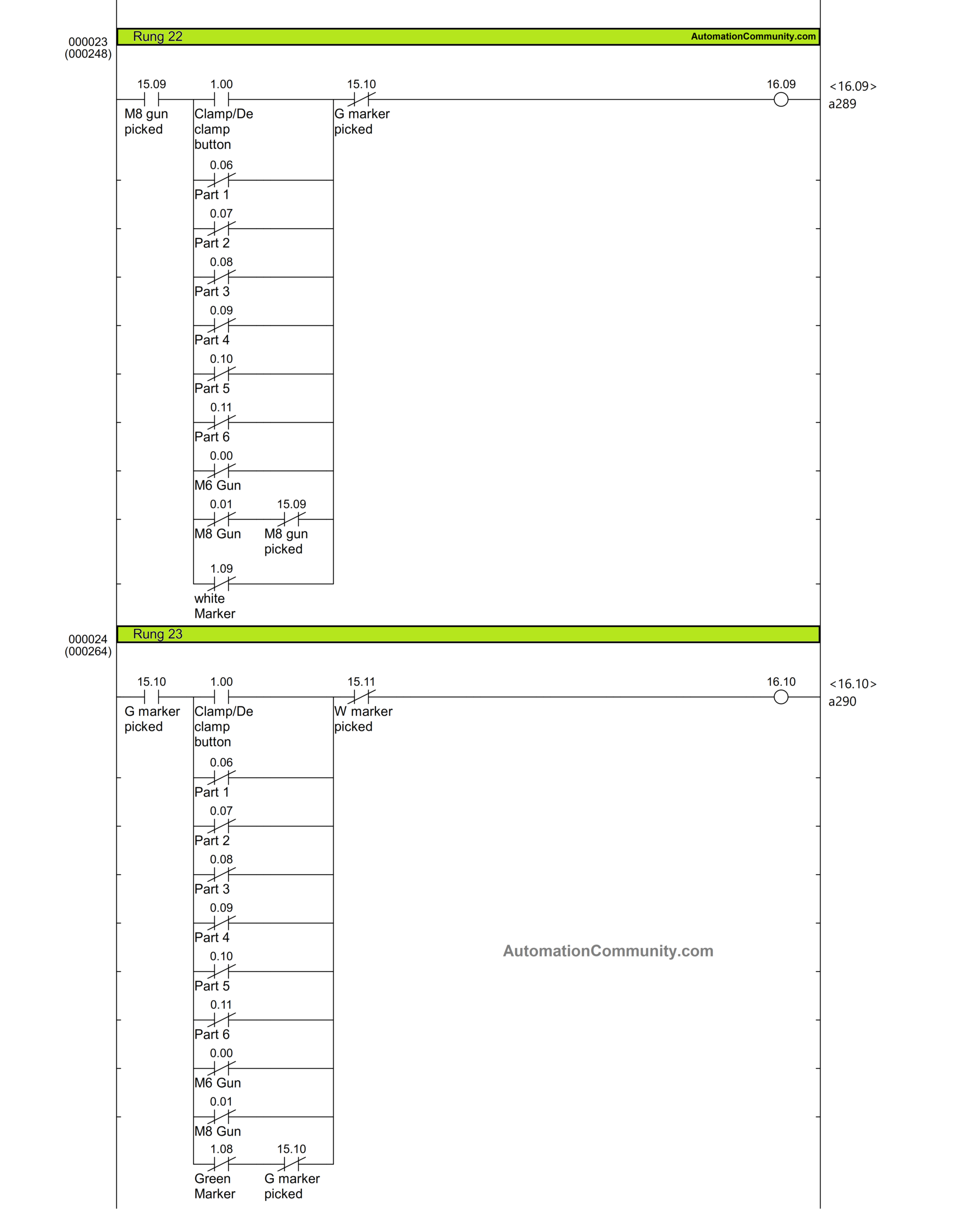
Rung 13 to 23
When a part or instrument is picked up incorrectly, and another one is picked up in its place, bits 16.00 to 16.10 actuate producing a buzzing noise.
For instance, in rung 14, Part 1 must be chosen at this time when 15.01 is high, meaning the fixture is unclamped. If any of the instruments or parts are chosen besides Part 1, a 16.01 actuates to noise buzzer using rung 24.
Additionally, it is ensured that 16.02 will not be activated if Part 1 is selected during its turn since the Part 1 input 0.06 is interlocked with 15.02 in series in rung 15. Similarly, the logic for other parts is written.
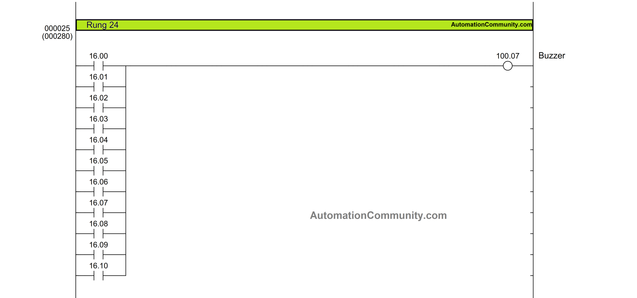
Rung 24
Any bit between the range of 16.00 and 16.10 that is active causes buzzer output 100.7 to activate.
Read Next:


Vivek
April 6, 2023Thank you