Reflex Flat Glass Level Gauge (RFG) – Pune Techtrol
Description
The Reflex flat Glass Level Gauges (RFG) are engineered to provide a reliable and clear visual indication of liquid level in vessels operating under high pressure and temperature conditions.
The level gauge features precision-molded prismatic grooves on the inner surface of the glass that comes in contact with the liquid. When light strikes the portion of the glass covered by a liquid, it is absorbed, appearing BLACK, while the portion covering the vapor space reflects light, appearing SILVERY-WHITE.
This creates a distinct, clear line that marks the liquid level and eliminates any chances of misreading.
Construction of Reflex Flat Glass Level Gauge
The construction of the level gauge involves several components. The liquid chamber is formed by a single-piece metal body, which is held together by ‘U’-bolts & nuts.
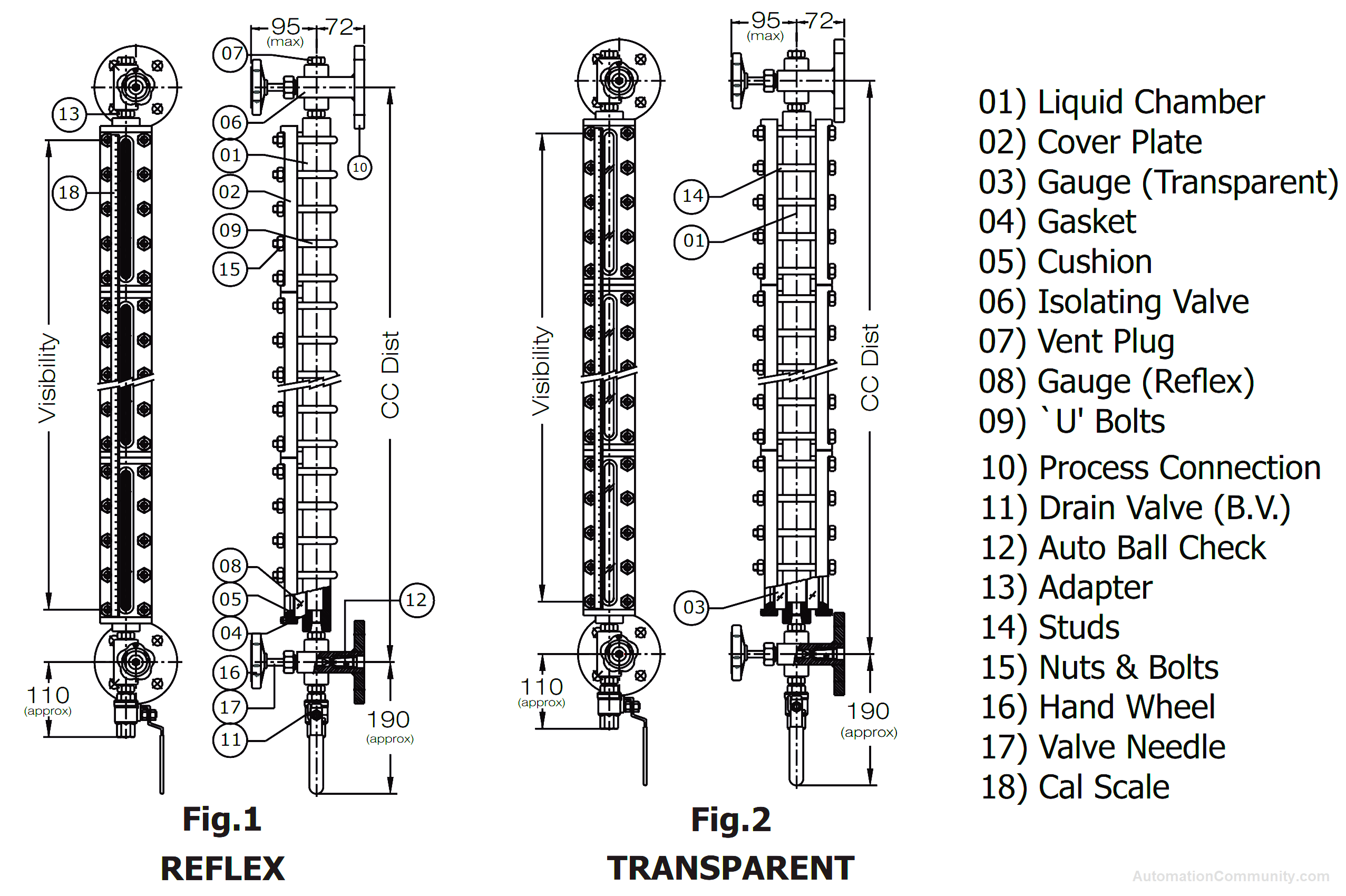
The reflex gauge glass is placed on the front side of the body, held in place by a sealing gasket, cushion, and cover plate. The glass is held in recesses machined in the body and cover plate, ensuring a leak-proof assembly and avoiding glass-to-metal contact.
The glass section is available in lengths from 190mm to 340mm, and up to 5 can be fitted in a single gauge assembly. For longer CC distances, two gauge assemblies can be coupled through a flanged coupler or installed in a staggered manner.
Shut-off valves are usually provided at either end of the gauge to isolate it in the event of glass breakage or replacement.
Installation of Reflex Glass Level Gauge
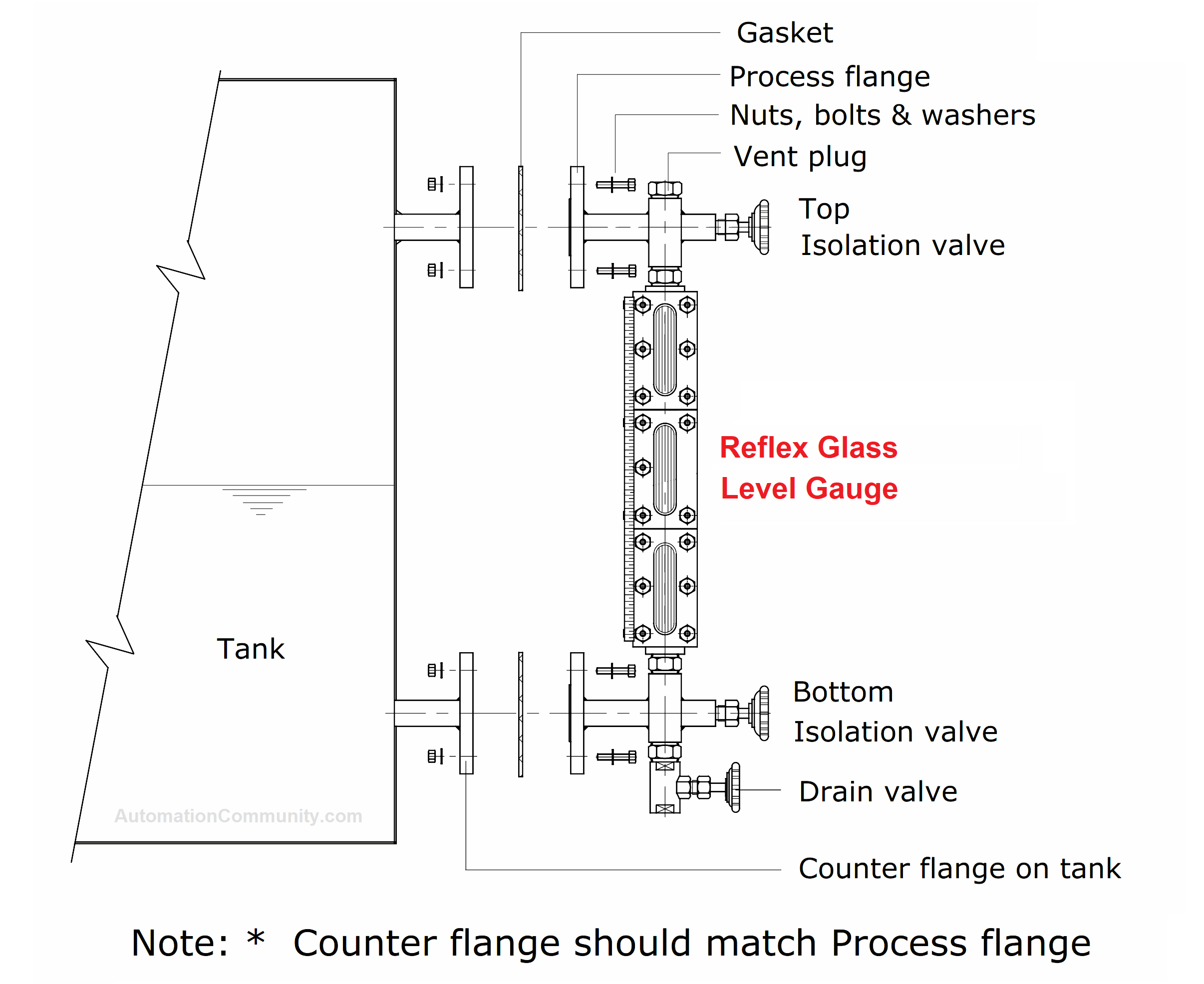
- Locate an appropriate spot on the tank with minimal vibrations.
- Check that the level gauge’s process connections match those on the tank. If using flange connections, make sure the flanges match and are oriented the same way. If using screwed or SMS unions, check that the threads and sizes match.
- Install the level gauge vertically and parallel to the tank side, using a plumb line to ensure proper positioning. Ensure the vent is at the top and the drain is at the bottom.
- Use suitable gaskets or thread sealant to prevent any leaks through the joint between the flanges or threads.
- Double-check that the vent, drain plug, and valve are securely closed.
Operation of Reflex Level Gauge
- Gradually turn the “Top isolation valve” to equalize the pressure between the tank and gauge.
- Gradually turn the “Bottom isolation valve” to allow the tank liquid to enter the gauge glass and search for its level.
- Wait for the liquid level in the gauge glass to stabilize. This visual representation will indicate the liquid level in the tank.
The function of Ball Check
The Auto Ball Check feature is designed to prevent liquid loss from the vessel and ensure safety in case of gauge glass breakage.
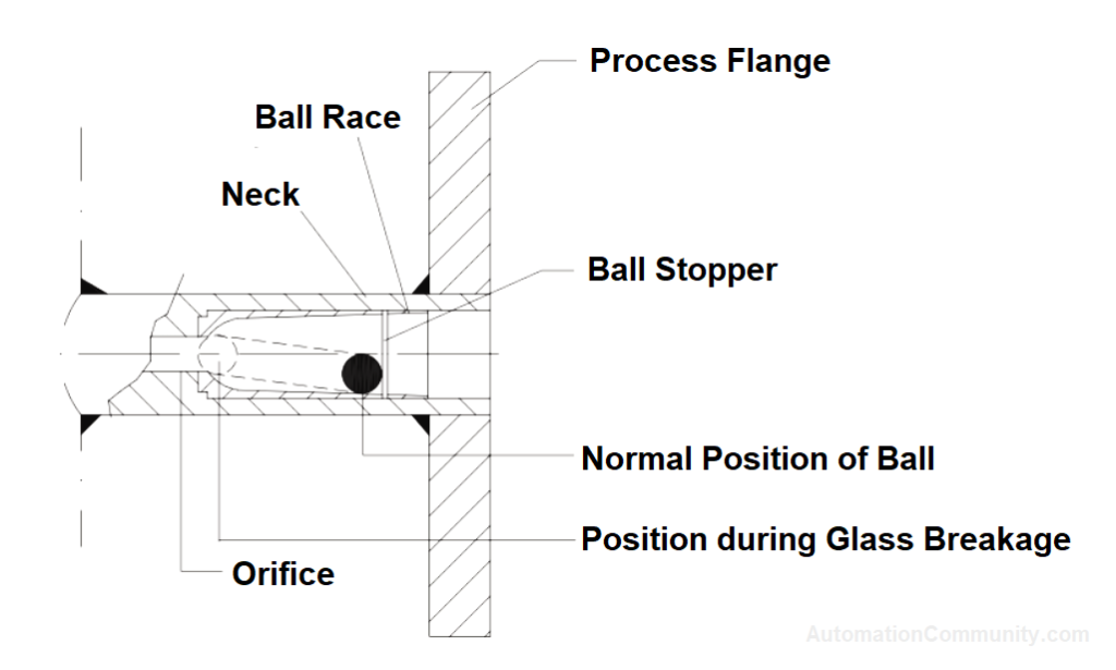
It includes a capsule situated along the “neck” of the gauge, which contains a ball that moves freely within its inner race between a stopper and an orifice.
In the event of a breakage, the pressure on the ball from the level gauge side will be atmospheric, while the higher pressure from the vessel side (Operating Pressure + Liquid Column) will cause the ball to move and block the orifice, minimizing liquid loss.
Maintenance of Reflex Level Gauge
The Reflex Level Gauge typically does not require maintenance. The gauge glass may occasionally become dirty and need cleaning with a soft brush, trichloroethylene, or compressed air.
We recommended you replace the gaskets once a year.
To clean the gauge glass without removing it, follow these steps:
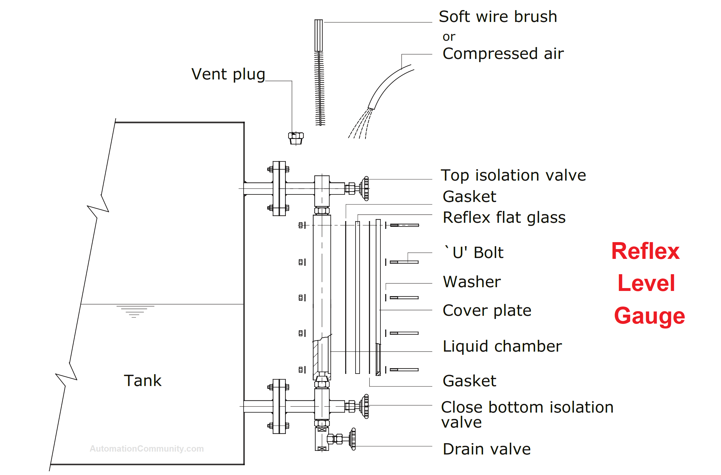
- Close both isolation valves.
- Open the drain plug/valve and drain the liquid from the chamber.
- Open the vent plug/valve.
- Clean the gauge glass with a soft wire brush or by passing compressed air or water from the top (vent). If dirt persists, use trichloroethylene.
To remove the gauge glass, follow the steps given below:
- Close both isolation valves.
- Open the drain plug/valve and allow the liquid chamber to drain completely.
- Open the vent plug/valve and then close the bottom isolation valve.
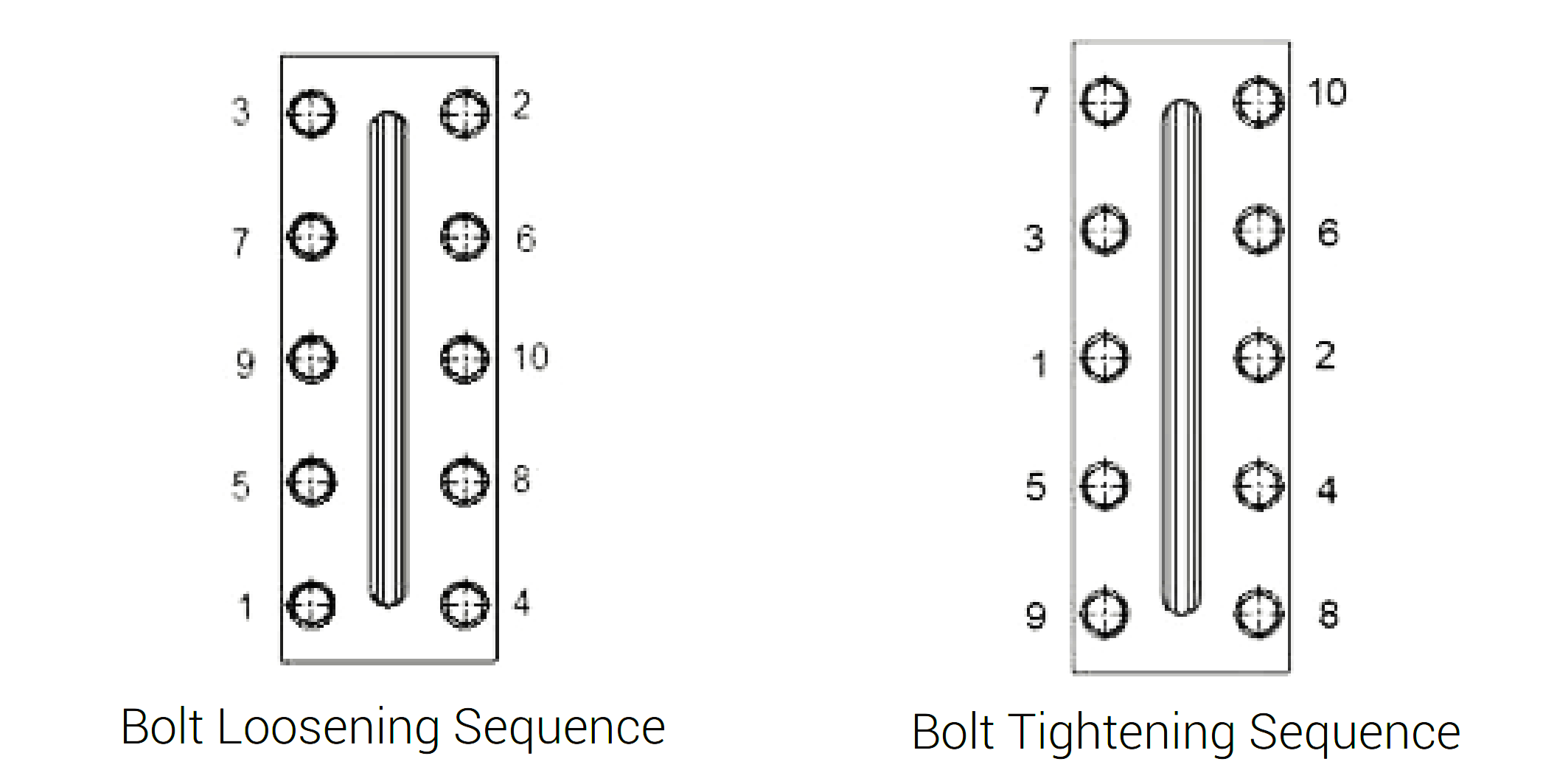
- Unscrew the nuts on the U-bolts located on the cover plate. Follow the bolt loosening sequence as shown in the below figure (left).
- Remove the mid-section U-bolts initially, and then remove the U-bolts on the upper and lower side. Carefully separate the cover plate.
- Remove the gauge glass, gasket, and cushion. Clean the gauge glass and liquid chamber thoroughly before reassembling.
To reinstall the gauge glass, follow these steps:
- Remove the old gaskets and install new ones. Place them in the designated recess.
- Carefully position the gauge glass onto the gasket.
- Secure the cover plate by fitting the U-bolts and tightening the nuts in the sequence shown in the above figure (right).
- Ensure that the U-bolts and nuts are tightened evenly with the appropriate amount of torque.
Troubleshooting of Reflex Level Gauge
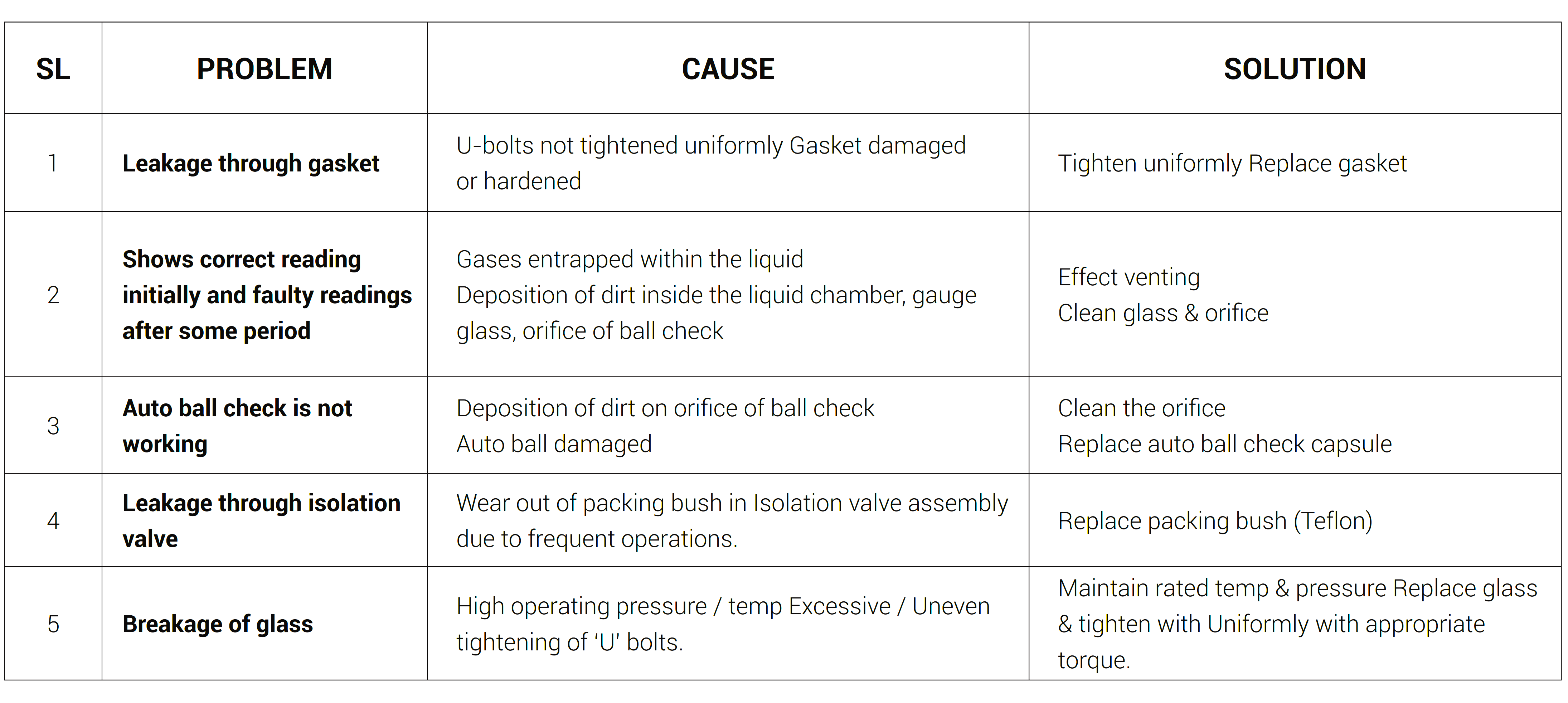
The most common problems and solutions of the reflex level gauges are mentioned in the below table.
Video
Location
Report abuse
Report abuse
Featured


