Description
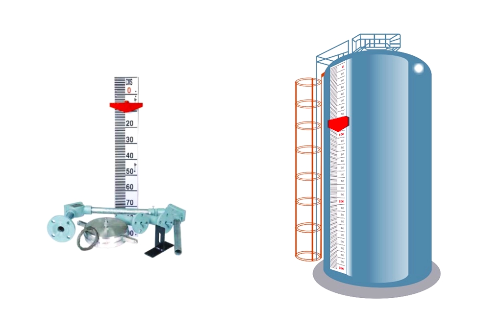
The float and tape level gauge measures liquid levels in atmospheric pressure tanks using a float and tape system.
Float and Tape Level Gauge
The Float and Tape level Gauge consists of a float attached to a steel tape with perforations, which is wound on a storage wheel equipped with a constant torque spring to maintain tension.
A gear mechanism moves the pointer to accurately indicate the liquid level.
 - Pune Techtrol 8")
The perforated tape engages pins on a sprocket pulley and is wound on a storage drum, while the rotation of the pulley is transferred to the pointer through the gear mechanism. To restrict horizontal float movement, guide ropes are anchored to the tank bottom.
This level gauge provides precise measurement of liquid levels during the vertical rise in the tank.
 - Pune Techtrol 9")
Float and Tape Level Gauge Specifications
- Measuring Ranges: 0-4, 0-8, 0-12, 0-16, 0-20 mtrs
- Accuracy: ±2mm
- Resolution: 1mm
- Min Liquid Sp. Gr.: 0.8
- Max. Temperature: 120°C
- Max. Pressure: Atmospheric
- Installation: Side / Top
- Dial Indicating Mechanism: 2 Pointers Dial (mm & meter indication)
- Calibration Dial: Aluminum (0D.210mm) white with graduations & numerical
- Dial Cover: Polycarbonate
- Pointers: Brass (Red Color) — mm indication, Brass (Black color) — meters indication
- Enclosure: Epoxy coated Cast Aluminium x IP65
- Process Connection: CS, A105 or SS304/316 x 1-1/2″NB, ANSI flange or -1-1/2″ BSP Socket
- Float: 350mm x SS316
- Tape: SS316
- Guide Rope: SS316 x 0 1.6mm
- Elbow Pulley: Cadmium-plated steel pulley with PTFE bush and SS shaft housed in WP Cast Al. encl.
- Protection Conduit (side-mounted): 40 NB, Galvanized steel (GI) or SS304 pipe, Horizontal limb= 800mm
- Tensioner: Cd pltd CS x CS Encl, SS304 Spring x SS304 Encl, SS316 spring x SS316 enclosure
- Tensioner Flange: 3/4″ NB ANSI flange (2 nos)
- Anchor: Weldable – SS316 or SS304 plate (25mm x 6mm thick) Weighted – SS316 or SS304 pipe (033mm)
- Drain: 1/4″ BSP Ball valve (side mtg)/plug (top mtg)
- Gauge Mtg Bracket: Epoxy-coated CS
- Seal Pot: Aluminium / SS, provided with sealant oil
- Hoist Mechanism: Provided on demand for high viscous liquid
Installation of Float and Tape Level Gauge
To install a float and tape level gauge, there are two options depending on the type of tank.
 - Pune Techtrol 10")
- For retrofitting on the existing tanks or new non-metallic tanks, a weighted anchor should be used.
- In the case of existing tanks, the gauge body should be mounted on a grouted pole since welding may not be allowed directly on the tank.
For proper installation of a float and tape level gauge, the tank must be emptied completely. When selecting the location for the gauge, ensure that no objects will obstruct the float’s movement. The float should also be positioned in a way that minimizes agitation. Mount the gauge’s nozzle away from the liquid fill pipe to prevent damage to the float and inaccurate readings caused by turbulence.
When installing a float and tape level gauge, it is important, to begin with, an empty tank. Choose a location where the float will not be obstructed by any objects and will experience minimal agitation. Mount the gauge’s nozzle at a safe distance from the liquid fill pipe to protect the float from damage and prevent turbulence from causing faulty readings.
Guide Wire Fixing
 - Pune Techtrol 11")
- To fix the guide wire, first pass the guide rope through the guide nozzles.
- Tie the upper end of the guide rope to the spring tension rod using a fastener, as shown in the figure.
- Bolt the tensioner flange onto the guide nozzle flange.
- Pass the open end of the guide ropes through the rope guide nozzle on the tank to prevent horizontal movement of the float.
- Tie the lower end of the guide rope to the anchor that is welded to the tank bottom.
- Remove both spring housings from the tensioner and tighten the tension adjuster nut to provide the guide rope with adequate tension.
- Refit the spring housing.
- Note that guide wire fixing is not required for floating roof tanks.
Level Gauge Indicator Setting
 - Pune Techtrol 12")
- To set the indicator for the actual liquid level, start by loosening the bolt on the front cover of the gauge to remove it.
- The gauge has two pointers: a longer black one for indicating in meters (‘mtr’) and a shorter red one for indicating in millimeters (‘mm’). Both pointers can be loosened by aligning the key.
- Begin by setting the shorter pointer at the division on the inner scale that corresponds to the two lower digits of the liquid level.
- Next, set the longer pointer at the division that corresponds to the higher digits plus the two lower digits.
- This will accurately reflect the actual liquid level in the tank.
Operation
- When taking the gauge into operation, it’s important not to let go of the float wire, as this could damage the float.
- Fill the tank with liquid and check the reading on the dial. Compare the reading with the dip measurement to ensure accuracy.
- If there is a large error, adjust the level indicating the pointer accordingly.
- Note that the correct installation of all mounting accessories on the tank is crucial for an accurate indication of the liquid level.
Seal Pot Assembly
A seal pot is provided for fuming liquids to prevent the venting of fumes into the air.
The seal pot comes pre-assembled with a protection conduit assembly.
 - Pune Techtrol 13")
After completing all installations, follow these steps for the seal pot:
- Make sure the drain plug and screw for the pulley on the seal pot are tightly secured.
- Open the pulley cover and pour non-volatile liquid, such as silicon oil, into the seal pot until it is completely filled. The conduit pipe connected to it should also be filled, as shown in the figure.
- The required amount of silicon oil for the seal pot is as follows: 50 mm WC = 1.5 Ltrs, 200 mm WC = 2.5 Ltrs.
- Fix the pulley cover back into its original position.
- Ensure that there is no leakage of oil from the seal pot.
Maintenance of Float & Tape Level Gauge
The common maintenance guidelines of float & level gauge are mentioned below.
- Regular inspections are necessary to ensure the gauge is in good working condition.
- Wipe the float to remove sediment particles and check for damages.
- Make sure the enclosure cover with its gasket is closed properly to maintain waterproofness.
- Check the movement of pulleys by removing pulley covers and cleaning them if necessary.
- Check for accumulation of liquid inside the gauge head by opening the drain plug and allowing it to drain out completely.
- Replace the drain plug after draining out the liquid.
- Optionally, use the hoist mechanism with a handle for easy maintenance or when dealing with highly viscous or solidifying liquids.
Troubleshooting Float and Tape Level Gauge
 - Pune Techtrol 14")

Featured