Description
Magnetic liquid level gauges (MLG) are often preferred for use in situations where glass gauges are not safe or practical. This is particularly true for liquids that are hazardous, flammable, toxic, aggressive, agitated, contaminated, or subject to high temperatures and pressures.
Magnetic liquid level gauges provide a reliable visual indication of liquid level, without the need for direct contact with the liquid. They work on the principle of magnetic coupling, with a float containing a permanent magnet that rises and falls with the liquid level, and an indicator mounted outside the tank that follows the movement of the float.
Magnetic Liquid Level Gauge Principle
The magnetic liquid level gauge is composed of a chamber and a non-magnetic float that is compatible with the liquid being measured. The float has a magnetic system that rides on the liquid level and is connected to an external visual indicator that comes in two designs.
- Magnetic Follower Capsule
- Bicolour Rotating Flappers
Magnetic Follower Capsule
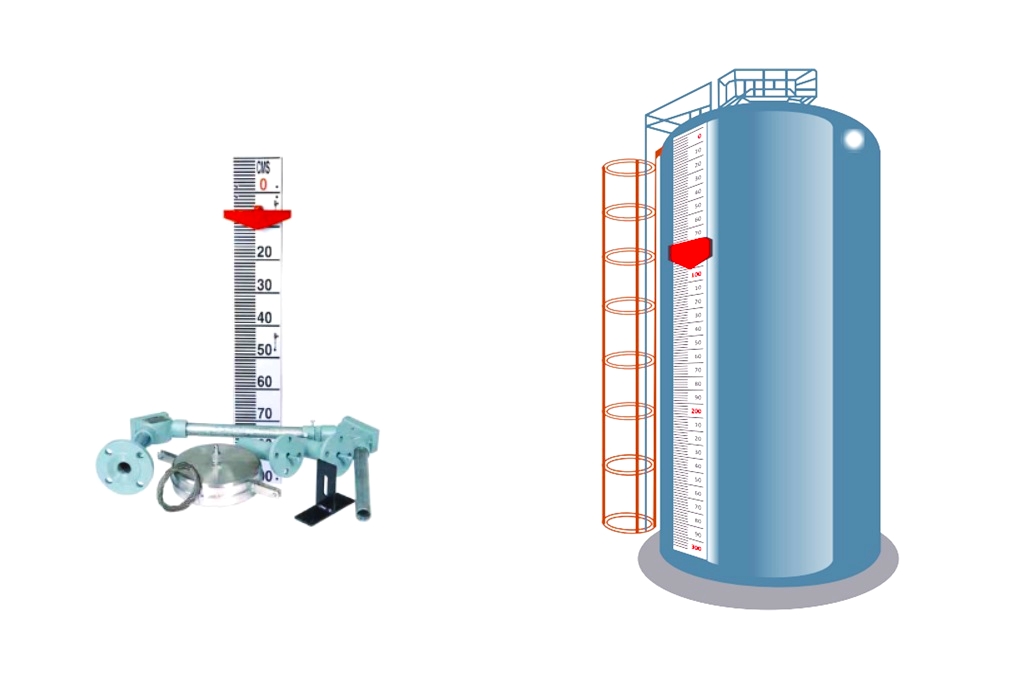
The magnetic follower capsule is made up of a red color and moves within a glass tube that is transparent and filled with water to minimize friction. The level is denoted by the white ring present on the capsule.
 - Pune Techtrol 7")
Bicolour Rotating Flappers
This design uses a RED magnetic follower capsule, which moves within a transparent glass tube filled with water and can be read against a scale. The level is indicated by the annular white ring of the follower capsule. The external visual indication is placed parallel to the chamber for side mounting and on top of the chamber for top mounting.
In the case of top mounting, the gauge’s construction is modified to include a dipstick-type float caged within a still well that moves as per changes in the liquid level. The magnetic system on the upper end of the float’s stem actuates the external visual indication.
Installation of Magnetic Level Gauge
For SIDE MOUNTING, follow these steps:
- Choose a location on the tank where vibrations are minimal.
- Ensure that the process connections and center-to-center distance of the level gauge match with those on the tank.
- Verify that the counter connections provided on the tank are vertical and in a plumb line.
- Install a separate isolating valve on the tank for safety and easy removal of the level gauge for repairs or maintenance.
- Keep a minimum clearance of 500 mm from the bottom nozzle to the ground for float removal or replacement.
 - Pune Techtrol 8")
For TOP MOUNTING, follow these steps:
- Choose a mounting location on the tank with minimal vibrations.
- Ensure that the mounting nozzle’s inner diameter is larger than the diameter of the float and the still well.
- When bolting or tightening, use a suitable gasket between the flanges and appropriate thread sealant between threads to prevent joint leakage.
- If using a Magnetic Follower Capsule, fill the glass tube with clean water and submerge the capsule in water.
- Ensure that the Follower Capsule or Flappers are properly connected to the magnetic float for accurate level indication. If necessary, use an external magnet to connect the float and the follower capsule.
- Before opening the isolation valve, ensure that the coupling between the float and the follower capsule/flappers is intact. If it is not intact, open the isolation valve gradually.
- Adjust the scale so that the zero marking corresponds to the dead liquid level in the gauge (i.e., the starting point of the float).
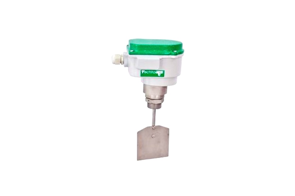
External Mounting of Switch on Gauge
 - Pune Techtrol 9")
- Make sure that all wiring is done correctly before turning ON the power.
- Adjust the position of the hose clamp to fix the switch at the desired location on the liquid chamber, ensuring that the cable gland position is downwards.
- Place the switch enclosure adjacent to the liquid chamber.
- Use a control unit to control resistive load by using a reed-type switch.
Maintenance
Maintenance is an important aspect of the proper functioning of liquid-level gauges. In cases where liquids contain dirt or suspended particles, it is essential to perform periodic cleaning of the float and the chamber. This will prevent the accumulation of debris, which may interfere with the float movement and affect the accuracy of the level indication.
Regular inspection and cleaning of the gauge components will also help to ensure their longevity and reliability.
Change of Float (Side Mounting Type)
To replace the float in a Side Mounting type level gauge, you should take care while removing the bottom flange to prevent damage to the float. After removing the flange, clean both the float and the chamber thoroughly.
When refitting the float, make sure that the arrow mark on the float is pointing upwards.
Change of Float (Top Mounting Type)
To replace the float in the top mounting type, first remove the instrument from the top of the tank, being careful not to damage the stem during the cleaning process. If the gauge has a follower capsule indication, ensure that the indicating glass tube is visible and clean, and refill it with water if necessary.
Additionally, confirm that the water level in the indicating tube is properly maintained.
 - Pune Techtrol 10")
Precautions
It is important to take precautions when using the float for liquid level measurement. The float is designed for a specific service based on liquid density and corrosivity. Therefore, it is important to ensure that the density of the service liquid is in line with the specifications given while ordering.
If you intend to use the gauge for a different service, it is advisable to consult the factory or ensure that the liquid density matches the float density and the liquid will not corrode the material of construction (MOC).
Specifications
- Installation: Side / Top
- Range (C-C DIST): Max. 3000mm (Magnetic follower capsule) Max. 5000mm (Bicolour rotating flappers)
- Level Indication: a) Red PP Follower Capsule -150°C in a Toughened glass tube (H2O filled)
b) Bicolour Rotating PP Flappers – 150°C (White & Red)
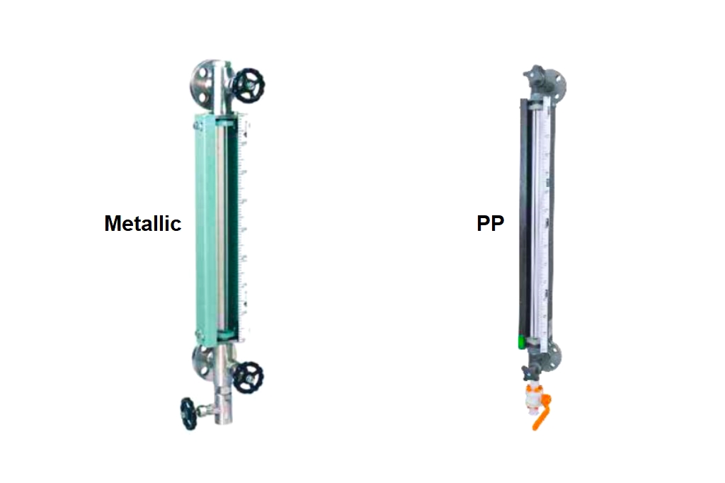
c) Bicolour Rotating Ceramic Flappers – 400°C (White & Red) Fitted externally to the float chamber - Float Chamber: Ø 60.3 mm in SS304/SS316/PP/PVDF
- Float: Ø 50 mm in SS316/PP/PVDF (for Side mounted) & Ø 75 mm in SS316/ PP (for Top mounted)
- Still Well: CS/SS304/SS316/PP (80NB)
- Calibrated Scale: White powder-coated Aluminium /SS (LC-10mm)
- Shut off Valve: 20 NB Ball/Globe Valves (SS)
- Isolation for Gauge: 25NB flanged Ball Valve (PP)
- Vent x Drain: ½” Threaded Plugs/Valves
- Process Connection: 1) 25NB/40NB/50NB Flanges for Side Mtd to BS/ANSI/DIN or 100NB Flange for Top Mtd. to BS/ANSI/DIN
2) ½”/ ¾”/ 1″ BSP or NPT (M/F) Screwed
3) ½”/ ¾”/ 1″ BSP or NPT (M/F) Union - Max Temperature: 70°C ( PP ) /100°C (PVDF)/400°C (SS)
- Max Test Pressure: 2 Kg/cm² ( PP/PVDF)/10 Kg/cm² (SS) or (at amb. temp): 100Kg/cm² (SS)
- Minimum Liquid Sp. Gr.: 0.7 – Side Mtd., 0.8 – Top Mtd.
Construction of Magnetic Level Gauge
 - Pune Techtrol 11")
Troubleshooting of Magnetic Level Gauges
Some of the common problems and solutions of magnetic level gauges are mentioned below.
 - Pune Techtrol 12")
WARNING: Operating the instruments outside the specified limits for pressure, temperature, voltage, and current may result in irreversible damage that cannot be repaired.

Featured