Description
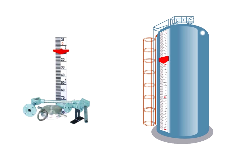
The Float & Dial Gauge is commonly utilized for underground tanks operating under atmospheric pressure. This gauge is equipped with both an analog and digital indicator.
Float and Dial Gauge
The analog type Float and Dial Gauge is designed with a float attached to a SS wire rope, which is wound on a drum carrying a constant torque spring housed in an IP66 enclosure to maintain tension in the rope.
As the liquid level changes, the float rises or falls and rotates the drum, which in turn moves a pointer over a calibrated dial to indicate the level in meters. This gauge can also come with two adjustable switches and/or a 4-20 mA transmitter as optional features.
 - Pune Techtrol 5")
The digital type Float and Dial Gauge works similarly to the analog type, with the difference being that the constant torque spring is housed in an Ex-d enclosure.
The gear motion induces a change in variable voltage signal, which provides both a digital level indication in various units (e.g. %, mm, cm, meters) and a 4-20 mA output. This current output can then be connected to a PLC/DCS through a current isolator.
 - Pune Techtrol 6")
The Float and Dial Gauge can be used in a variety of applications including measuring the level of raw or treated water, sewage, effluent, oil, HDO (high-speed diesel oil), LDO (low-speed diesel oil), and various solvents.
The gauge is suitable for use in underground tanks under atmospheric pressure.
Checking of Float and Dial Gauge with Analog Indication
Here are the step-by-step instructions for checking the Float and Dial Gauge with Analog Indication:
- Manually pull out the wire rope and make sure that the pointer moves smoothly on the dial. Then release the wire rope slowly to prevent kinks and ensure that it does not slip out from the pulley.
- The pointer should indicate “Full Measuring Range” on the dial when the wire rope is fully wound and the float is at its highest position. It should indicate “0” when the wire rope is extended up to its measuring range. If there is an error, loosen the pointer and set it at “0” on the dial or calibrate it to zero.
- Micro switches are set for high and low levels of the measuring range. Open the terminal enclosure and connect a continuity tester between the P and NO terminals. Slowly pull out the wire rope and observe the continuity (changeover) between P and NO at the required level set point.
- The transmitter output is pre-calibrated at the factory based on the tank height and nozzle length specified by the customer. Open the terminal cover and connect a 24 VDC supply to the +ve and -ve terminals of the transmitter card through a multimeter in series.
- Observe 20 mA on the multimeter when the pointer shows the full measuring range on the dial (tank full condition). Slowly pull out the wire rope until the pointer shows “0” on the dial/display and observe a gradual decrease in current. It should show 4 mA when the pointer/display is at “0” (tank empty condition).
Checking of Float and Dial Gauge with Digital Indication
To check the Float and Dial Gauge with Digital Indication, first, open the terminal cover and connect the 24 VDC supply to the positive and negative terminals of the transmitter card through a multimeter in series, as shown in the figure.
Next, observe the 20 mA on the multimeter and check if the indicator shows the full measuring range when the wire rope is fully wound and the float is at the topmost position, indicating a tank full condition.
Then, slowly pull out the wire rope and note the gradual decrease in current and display readings. At the tank empty condition, the indicator should show ‘0000’ and the current should read 4 mA.
If there is any error, follow the calibration procedure.
Operation
To ensure accurate level indication, it is crucial to properly install all mounting accessories on the tank. Begin by checking that the gauge reads zero when the float is at the bottom of the tank.
Then, fill the tank with liquid and compare the reading on the gauge with the dip measurement. If there is a significant error, adjust the level indicating the pointer accordingly.
Keep in mind that proper installation of mounting accessories plays a crucial role in achieving accurate level indication.
 - Pune Techtrol 7")
Float and Dial Gauge Calibration
The Float and Dial Gauge with analog indicator can be equipped with an optional transmitter, while the FDG with digital indicator already has a default 4-20 mA output.
The transmitter output is pre-calibrated by the factory to match the specific measuring range provided. You can re-calibrate the transmitter if required.
Follow the following steps to calibrate the transmitter.
- Open the terminal enclosure cover and locate the 4-20 mA converter card inside.
- Connect a 24 VDC supply to the supply terminals with a multimeter in series.
- Empty the tank and observe that the gauge indicates ‘Zero’ on the dial or display, and the current output shows 4 mA on the multimeter.
- Fill the tank to its full measuring range and observe that the level gauge indicates ‘Full’ on the dial or display, and the current output shows 20 mA on the multimeter.
- If a minor difference is observed in the current output, adjust 4 mA with the ‘Zero’ trim pot when the tank is empty and 20 mA with the ‘Span’ trim pot when the tank is full.
Specifications of Float and Dial Gauge
General
- Installation: Top
- Process Conn. Size: 3” NB ANSI 150# or 4” NB (with Stillwell)
- Process Conn.MOC: CS, SS304/316, PP, ECTFE (Hallar) coated SS316
- Wire Rope: Ø 1.6 x SS304/316/316L, PTFE insulated SS316
- Float MOC: SS304/ 316/316L, ECTFE (Hallar) SS316
- Float Size: Ø73 x 240H cylindrical
- Liquid SG: ≥ 0.8
- Temp Range: -10 to 100°C
- Pressure: Atmospheric
- Indication: Analog or Digital
Analog Indicator
- Ranges: 0-1, 0-2, 0-3, …..or 0-10 mtrs
- Dial Enclosure: Cast Al, powder coated., IP66 protection
- Terminal Enclosure: Cast Al, powder coated., IP66 protection
- Cable Gland: PG9, Polyamide
- Calibrated Dial: Al, white powder coated with black graduations & numerical
- Pointer: Al, red powder coated
- Accuracy: +/- 50 mm
Adjustable Alarm Switches (Optional)
- Alarm Switch Type: Microswitch – SPDT,
- Rating: 5A, 250 VAC
- Switch Action: Mono-stable
Transmitter (Optional)
- Supply: 24 VDC
- Output: 4 – 20 mA (2wire) x 400 Ohms Load
- Accuracy: +/- 2% FS
Digital Indicator
- Range: 0 to 10 meters (decimal pt. selectable)
- Dial Enclosure: Cast Al. Ex d Gr IIB
- Cable Gland: ½” NPT, Double Compn, Brass
- Display: 4 digits, 7 segments LED (1”)
- Programming: Through keypad
- Accuracy: +/- 2% FS
- Supply: 24 VDC
- Output: 4 -20 mA (4 wire ) x 300 Load
Accessories
- Still well: 3” NB pipe, with 4” NB ANSI 150 # flange in CS, SS304/316, or PP
Problems and Solutions of Float and Dial Gauge
 - Pune Techtrol 8")

Featured