Hydraulic Clamping System using PLC Ladder Logic
Learn about the Hydraulic clamping system and circuit with the help of PLC ladder logic and analysis of the cylinder stroke length.
Hydraulic Clamping System
Many manufacturing industries use hydraulic methods for clamping the workpiece for doing operations like pressing, drilling, milling, etc.
The main advantage of using the Hydraulic method is, this, we can generate more amount of pressure for clamping a large amount of mass compared to other mediums like pneumatic or electrical.
Hydraulic is the method which uses fluids like oil for moving the output with the help of valves and actuators.
In our operations, we use cylinders for clamping the piece with an automatic retraction with the help of a PLC control system.
Components Used
- Double Acting Cylinder
- 4/3 Solenoid Valve
- Unidirectional Pump
- Motor
- Proximity Sensors
- Pressure Relief Valve
- Reservoir
- Push Button
- PLC Cards (Input & Output)
Double Acting Cylinder
Double Acting cylinder is one of the actuators in hydraulic. The cylinder does the actuation by moving in linear ways.
The name “Double acting” indicates, its TO and FRO movement can be controlled mechanically, manually, or electrically. It has two ports one for forward movement and another for reverse movement.
4/3 Solenoid Valve
The movement of the cylinder is directed by the directional control valves only. In our application, we use a 4/3 solenoid-operated Directional Control Valve.
As we are controlling electrically, we need to use the solenoid valve. And 4/3 means, 4 indicates the 4 ports and 3 switching positions.
If the supply comes forward movement means one switching position activates or the supply comes in reverse means another switching position will activate. If no supply comes means, the valve comes to its neutral position (Ports will be blocked).
Unidirectional Pump
The pump is the source for the operation of the hydraulic system. This enforces the fluid from the tank to get into the system for performing the required operation in the system.
Unidirectional Pumps will deliver the fluid in one direction only.
Motor
The motor is the driving element for the pump. This makes the pump to drive the fluid, and without the help of the motor, the pump does not drive the fluid to the system.
Proximity Sensors
Proximity sensors are used to detect the object without getting contact. These sensors have many types like inductive which detects metals, capacitive which detects any objects, and photoelectric where light is used for detection.
In our application, we use an inductive proximity sensor which is used to detect the end position of the cylinder. By sensing the cylinder’s end position, we can get the input that the process is done.
Pressure Relief Valve
A pressure relief valve is used to relieve the interior pressure in the system by clearing the excessive unused oil or fluid in the system to the reservoir
Reservoir
The reservoir is nothing but the collecting tank for the system. From the valves, pumps the excessive and return oils were collected in the reservoir only.
From the reservoir, the oils were transferred to the input tank where the pump is fixed.
Push Button
The push button is the input element for giving the starting signal for the system.
Here 1 Normally open push button is used for starting the function in the system which is connected to one of the PLC inputs.
PLC Cards
Every PLC has input and output cards where all the inputs and outputs were connected. In our function, we have used general PLC which has 8 inputs and 8 outputs.
PLC cards are simply nothing but connection parts of input and output, by which the specific operations were performed. This PLC has a power supply of 24V DC
Hydraulic Circuit
Below given Hydraulic circuit is used for the clamping process. We used two cylinders for pushing the workpiece from either end. a1, a2, b1, and b2 are four proximity sensors used in the circuit for sensing the positions of cylinders.
Two 4/3 solenoid valves of solenoids s1, s2, s3, and s4 were used for the movement of the cylinders. And the power source of fluid is given by the unidirectional pump which was driven by the motor.
The connecting lines represent the connectors or hoses from which the fluid passages over the different components for doing the actuation.

PLC Wiring and Connections
For this application, we used PLC which works under the supply of 24V DC and it has 8 inputs and 8 outputs.
We have used 5 inputs, one for the push button & four for proximity sensors, and 4 outputs for the solenoid coil.

L1 represents the push button (Normally Open contact), and a1, a2, b1, and b2 were proximity sensors. S1, S2, S3, s4 were solenoid connections.
We used a general PLC connection; we can use this connection to any PLC for doing this clamping operation.
Just we want to check the selection criteria like power supply and the number of inputs and outputs.
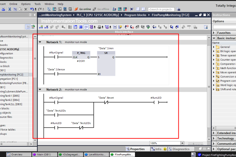
Ladder Diagram
Below given Ladder Logic is used for the clamping application for the PLC connection.
Here we use general logic symbols for this operation.

Working
When the hydraulic system turns, the pump will prime the fluid into the system. The fluid gets inside the valve and gets ready for the cylinder movement.
Since the cylinder movement is not moved from the original position, the excess fluid driven by the pump will produce more pressure.
So, by using the pressure relief valve excess fluid is returned back to the reservoir.

Now, the cylinder movement wants to be done. The Solenoid valve is the element that makes the cylinder movement. Here solenoid valve is energized by the inputs like push buttons and proximity sensors in the PLC.
When Push Button L1 is pressed, the proximity sensors a1 and b1 were already in contact so it will produce a signal and this connection makes the output 0 and output 2 energize in the PLC. Suitable PLC execution is exactly done by the ladder logic.
In Ladder logic, the NO contact L1 is activated it makes the signal to out0 and out1 in the PLC, because out 1 and out 3 are in the normally closed position

Out 0 and Out 2 give the signal to solenoid 1 and solenoid 3 which makes the cylinder move forward. Now the clamping function is done.
In this, the fluid will moves the cylinder pistons to extend forward with great pressure.
At this time the pressure relief valve will be in a normal position because the maximum obtaining pressure will be used in the cylinders. Then the return fluid is drained into the reservoir with the help of valves.

Once its forward motion is done, its position was sensed by the proximity sensors a2 and b2. The signal from a2 and b 2 makes the out 1 and out 3 activate as per the ladder logic.
Out 1 and Out 3 make solenoid 2 and solenoid 4 activate which makes the cylinder come back to its home position. In this main aspect, we need to cut the signal of out 0 and out 1.
If we are not cut the signal of out 0 and out 2 means the cylinder will not move back because if the signal comes from both sides of the solenoid valve means the valve will not function as per the requirement.
So, we cut the signal by placing the normally close contact of out 1 and out 3. When the cylinder touches the a2 and b2 sensor means it gives the signal to out 1 and out 3 will automatically cut the signal of out 0 and out 2.


Now, the clamping function is over. The cylinder moves forward with the help of the push button and it retracts with the help of a proximity sensor. We can make this automatically with the help of a timer. After one cycle with a specific time, it will do the process automatically.
Once the push button is pressed the number of actions will be done continuously with a specific delay. But we designed a circuit for manual operation only, depends on our needs we can modify the circuit and logic
In this, we also analyzed the movement of the linear motion of the cylinder with the plotter. By considering the time in the x-axis and stroke length in the y-axis we can check at the time duration, and how the stroke length is. This analysis can help us to check the cylinder functionality and operating capability & reliability.

Conclusion
In this, we have seen the clamping process hydraulic circuit with the help of PLC and also the analysis of the stroke length of the cylinder with the cylinder. This process is majorly used in the manufacturing field for pressing the stack and clamping the objects in drilling, milling, and CNC machines.
Read Next:


Comments
1
Thanks for the detailed information