In this article, you will learn the PLC programming for interfacing with LVDT for metal tube length measurement for different sizes and applications.
PLC Programming Length Measurement
The tube ends are coupled with a flange yoke using a hydraulic pressing machine.
With this application, a poka-yoke is to be introduced in such a way that the hydraulic motor trips if the measured length of the tube goes beyond its desired length with a tolerance of one millimeter.
This means, if a particular model is to have a standard length of 791 mm, then the actual measurement must be in the range of 790 mm to 792 mm. If it goes beyond its mentioned range, then the hydraulic motor is tripped.
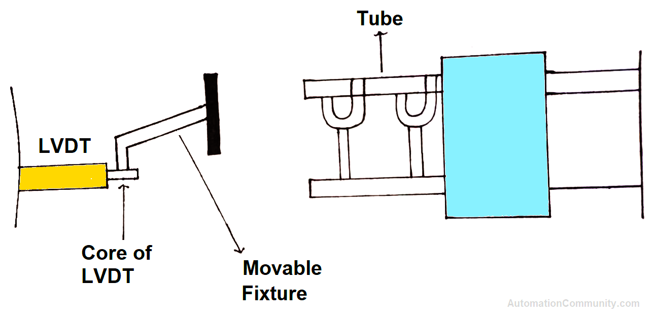
To measure the length of a metal tube, a mechanical arrangement is built in such a way that the core of LVDT can be moved manually by hand in both directions.
Also, when the manually movable fixture touches an end of the tube, the actual measurement of the tube is displayed on the HMI screen.
This measured length is compared with the standard length allowing the tolerance of 1 mm.
As discussed above, a hydraulic motor is tripped or stays on accordingly.
The comparison is only made when the proximity sensor is sensed and it is fitted in its place in such a way that it senses just as the movable metallic fixture touches an end of the tube.
Before the movement of the metallic fixture, the concerned model must be selected in HMI. This is discussed later in the article when the PLC program is explained.
See the video and image below to understand the arrangement briefly.
The video does not contain any poka-yoke inclusion with the application. Only a brief understanding of the arrangement is shown.
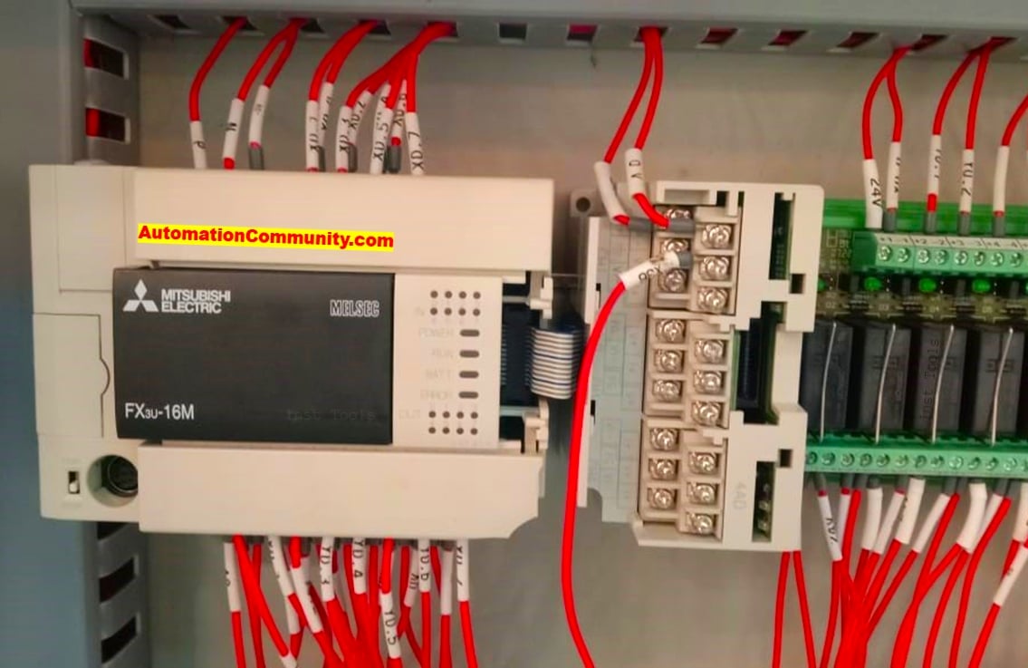
Now, here we are using Mitsubishi PLC FX 3U and delta HMI DOP 107 CV.
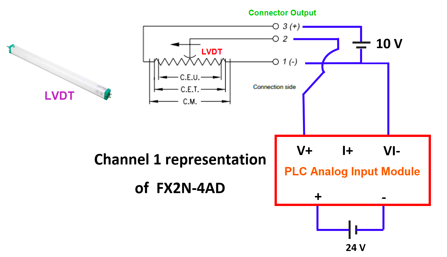
Also, for LVDT configuration, we are using FX2N-4AD as an analog input card (module). Channel 1 of this card is used for LVDT.
LVDT provides 0V to 10V or -10V to +10V DC respectively when its core is pulled or pushed. This voltage output will become an input to channel 1 of the analog input card.
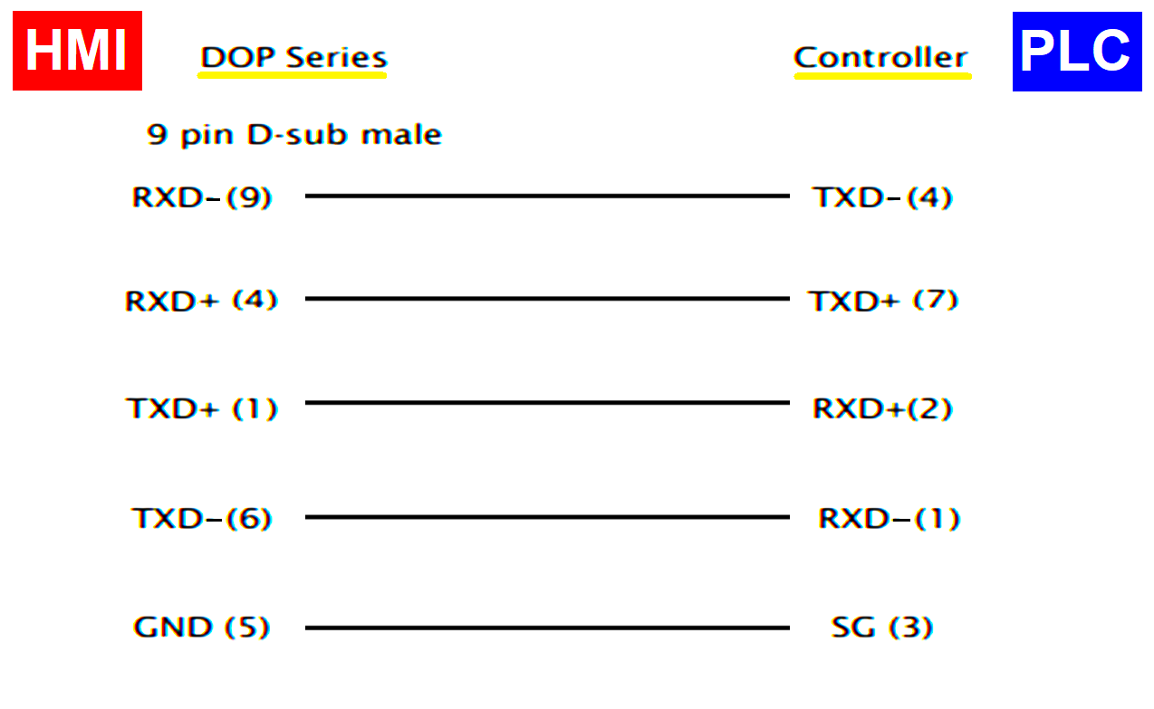
PLC and HMI Wiring
Now, prior to PLC logic, see the image below for communication of PLC with HMI. The communication is on RS 422 protocol.
LVDT Wiring Connection with PLC
Also, see the wiring connections of the PLC analog input card with LVDT in the figure below.
The figure below only shows the physical location of the cards.
Metal Tubes
Now, there is a group of models (tubes) to be measured before the coupling process.
Look at the standard length of tubes as different models.
- Mega – 791 mm
- Dicor – 828 mm
- BS III – 924 mm
- BS IV – 974 mm
- Intra V10 – 795 mm
- Intra V30 – 1034 mm
- Intra V50 – 1074 mm
- 900 CC – 982 mm
- BS VI – 989 mm
The division of groups is as follows:
- Group A consists of BS III, 900CC, Intra V50, and BS-VI
- Group B consists of Intra V 30 and Intra V50
- Group C consists of Mega, Dicor, and Intra V 10
Observe the following arrangement again
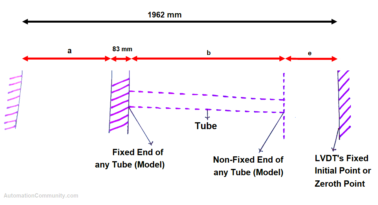
- “a” is a variable for each group.
By physical measurement, the variable “a” is found to be
- 830 mm for Group A
- 647 mm for Group B
- 1027 mm for Group C
The total length from one end (fixed) to the initial position of LVDT is 1962 mm.
“e” is the total length traveled by the core of LVDT which is equal to D12 in the PLC program.
“b” is the total measured length of the tube.
Only one tube from each group is measured here.
According to the schematic, mathematical equations for different groups are as follows:
For group A, the equation is:
830+ 83+ b+ e = 1962 or b = 1049-e
For group B, the equation is:
647+ 83+ b+ e = 1962 or b = 1232-e
For group C, the equation is:
1027+ 83+ b+ e = 1962 or b = 852-e
Now moving toward the PLC program:
PLC Programming
A separate start and stop push-button is used to run and stop the hydraulic motor.
- X4 – Hydraulic start
- X7 – Hydraulic stop
- X2 – Sensor feedback
- Y7 – Motor output
Used Data registers are explained in the Rung descriptions.
Rung 1:
“FROM” instruction is used to read the analog value of LVDT.
- K0 defines the first extension module (FX2N-AD)
- K5 defines the first channel of FX2N-4AD to be read as an average value. If K9 is used instead of K5, then it would read the present value which varies rapidly, so K5 is used to read its average value.
- D0 stores the read value in decimal.
- Kx at the last defines the number of channels to be read, here x=1, which means the first channel only
Note: As the input signal is -10V to +10V, we can set channel 1 to voltage mode. It is by default set to voltage mode. Use the instruction below in addition to FROM instruction for setting the channel to voltage mode when required:
TO K0 K0 H0000 K1
The H0000 represents all four channels set to voltage mode.
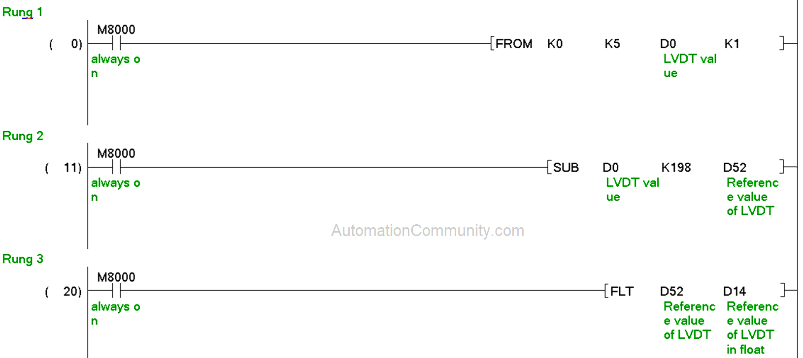
Rung 2:
198 (Dec) is subtracted from D0 (LVDT’s current value) and stored in D52.
Now, at its initial fixed point, LVDT attains zero value stored in D52.
Rung 3:
D52 is converted into its float value and stored in D14.
Now, before moving to the fourth and fifth rungs, emphasize physical measurements and analog values.
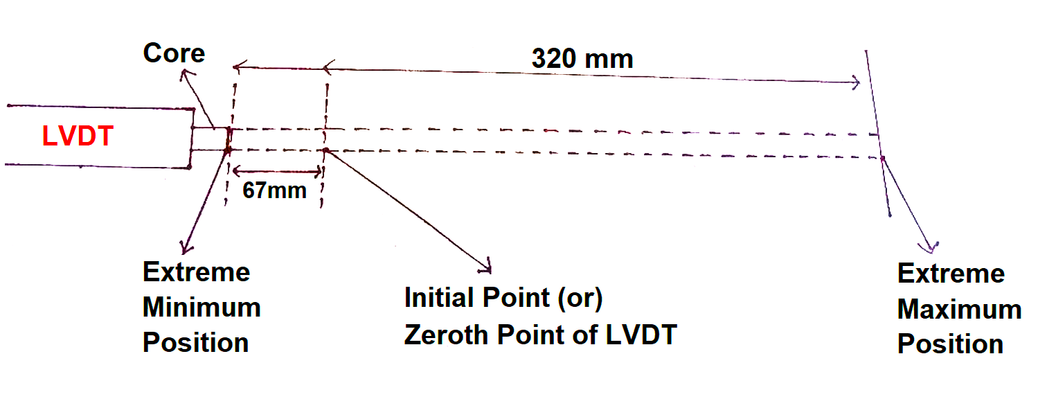
Let the length traveled by the core of LVDT be x mm.
- When x = 67 mm, the analog’s decimal value is 198.
- When x = 320 mm, the analog’s decimal value is 2265.
Rung 4 & 5:
Applying the unitary method in the 5th rung such that the difference of maximum and minimum distances is equal to the difference of their respective analog values.
Thus, 1 (one) decimal value should be equal to 253 divided by 2068 which gives 0.12234 (float).
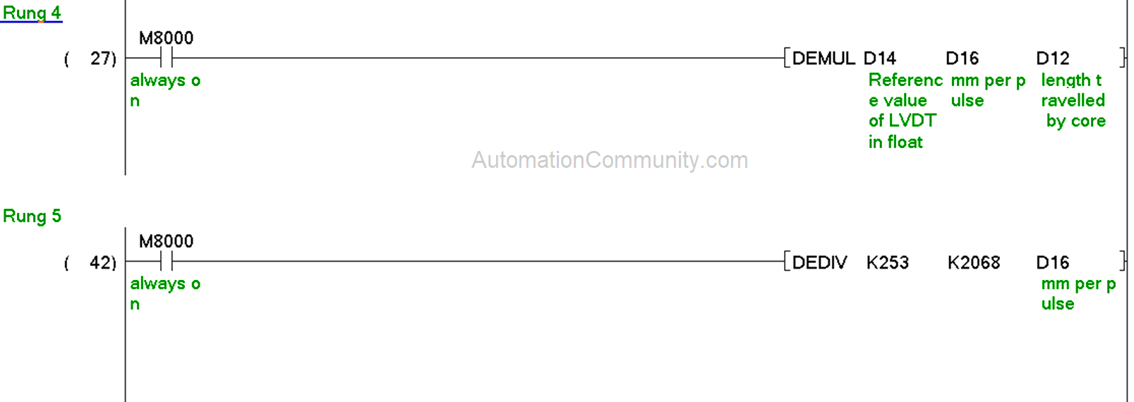
This value is stored in D16 which is multiplied by the reference value (current value) in D14, the result of which is stored in D12 to give the exact value of length (in mm) traveled by the core from its initial point to any distance in rung 4.
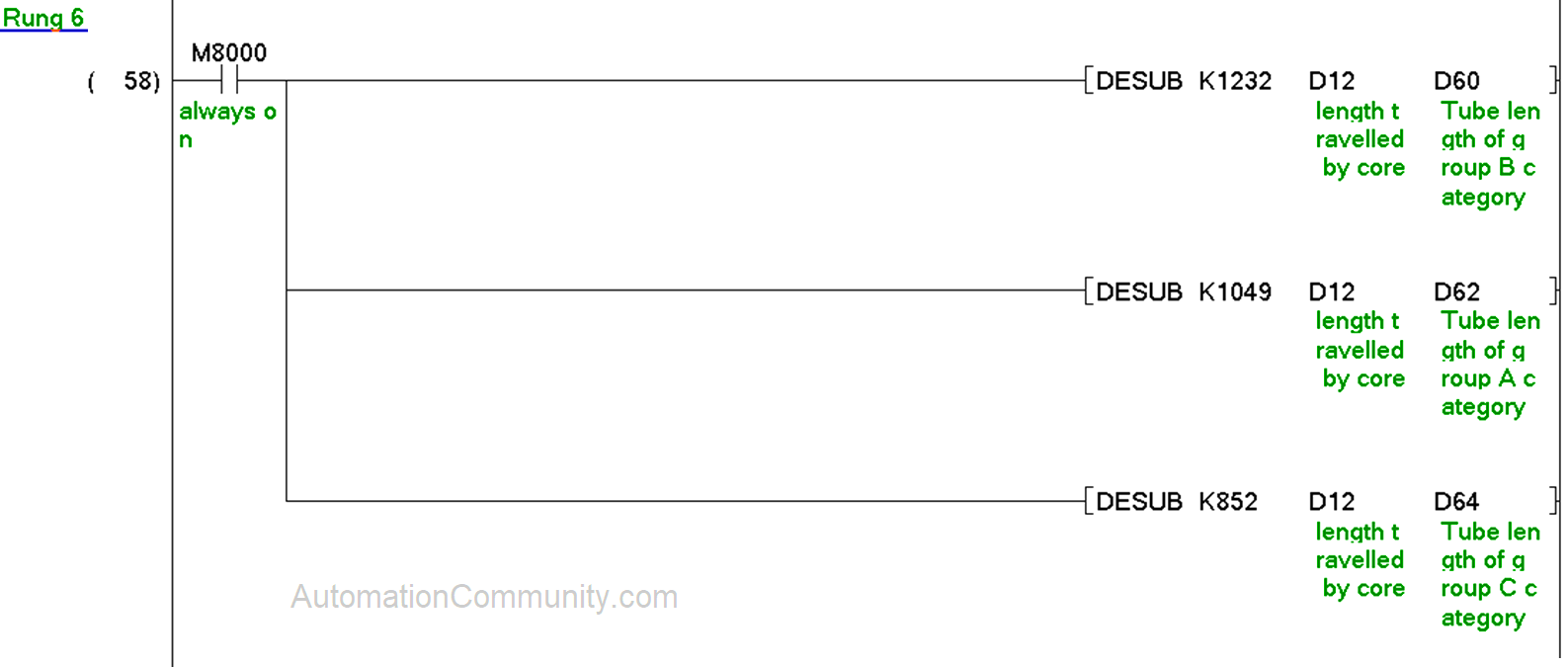
Rung 6:
D62, D60, and D64 are the variable lengths equated as a result of discussed Group B, A & C equations.
- D62=b (for Group A)
- D60=b (for Group B)
- D64=b (for Group C)
- e is discussed above.
Now, as discussed above one tube is to be measured from each group, and a tube from Group B is measured here in the 7th to 10th rungs.
Rung 7 & 8:
Intra V50 is measured from the Group B category. 1075.0 (float) and 1073.0 (float) are moved in D54 and D56 in rung 8 to define the accepted(permissible) range of Intra V50 as its standard length is 1074 mm. Thus, the range includes tolerances of +- 1 mm.
The model should be selected from HMI through M31.
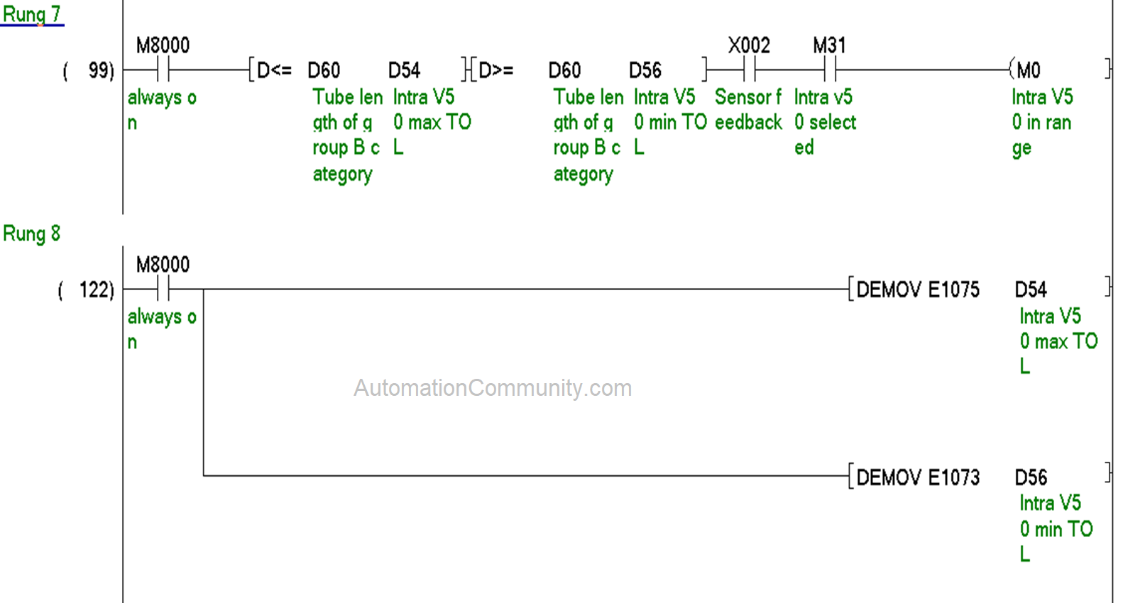
When X2 is high, it indicates that the metallic fixture has touched an end of the tube. At this time, the value of D60 should be in the range of D54 and D56. When this is true, M0 is high in rung 7, indicating the length of Intra V50 is in the permissible range.
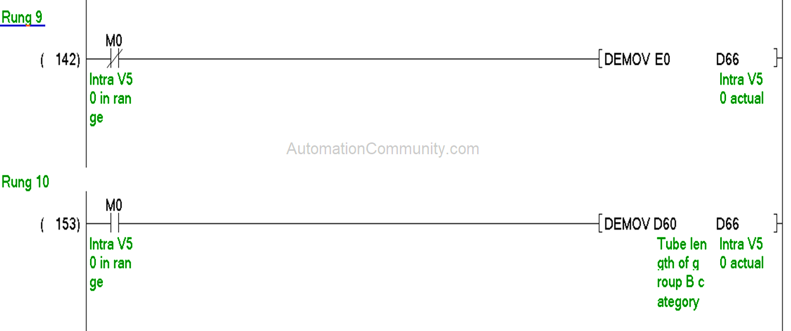
Rung 9 & 10:
When M0 is high, the value of D60 is moved to D66 which shows the actual length of Intra V50 in rung 10.
When M0 is low, D66 always holds a zero (0) value through rung 9.
This means the length of Intra V50 is displayed on HMI through data register D66 only when M0 is high.
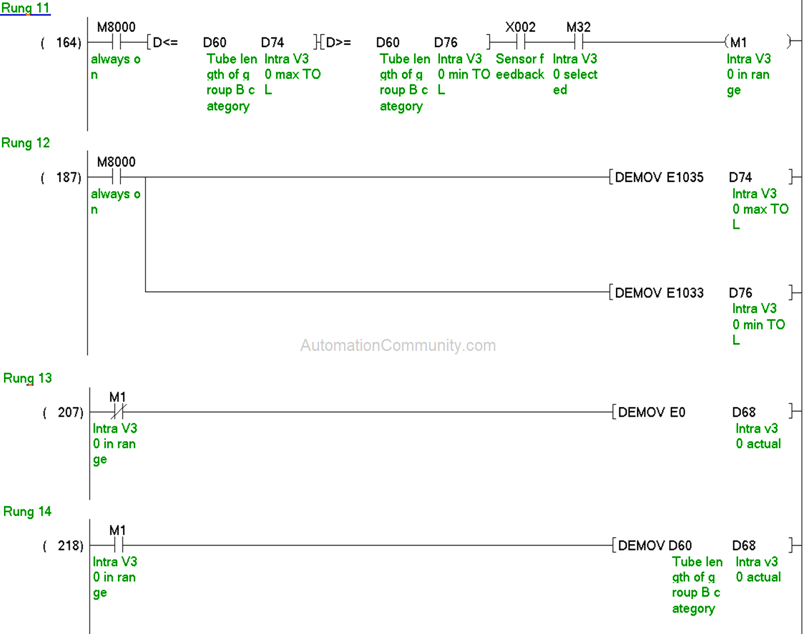
Rungs 11 to 14:
Similarly, Intra V30 of the Group B category is measured in rungs 11 to 14.
Now moving to the Group A category
Rung 15, 16,17 &18:
D84 and D86 hold the permissible limit of 900cc model in rung 16. If the value of D62 goes in the permissible range at the time of sensor feedback after the model selection.
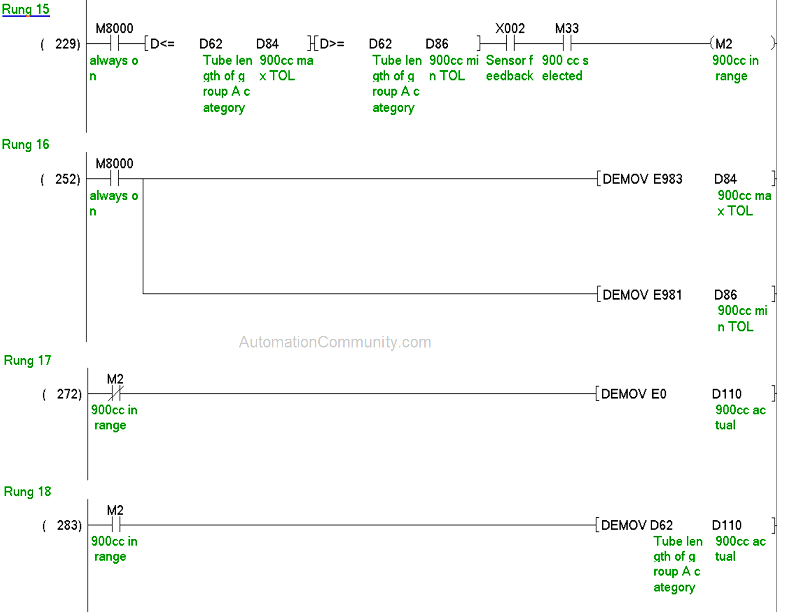
Then M2 is actuated, following which the value of D62 is moved in D110 in rung 18 to show the actual length in HMI.
If 900cc is out of range, then M2 is not actuated following which the value of D110 stays zero.
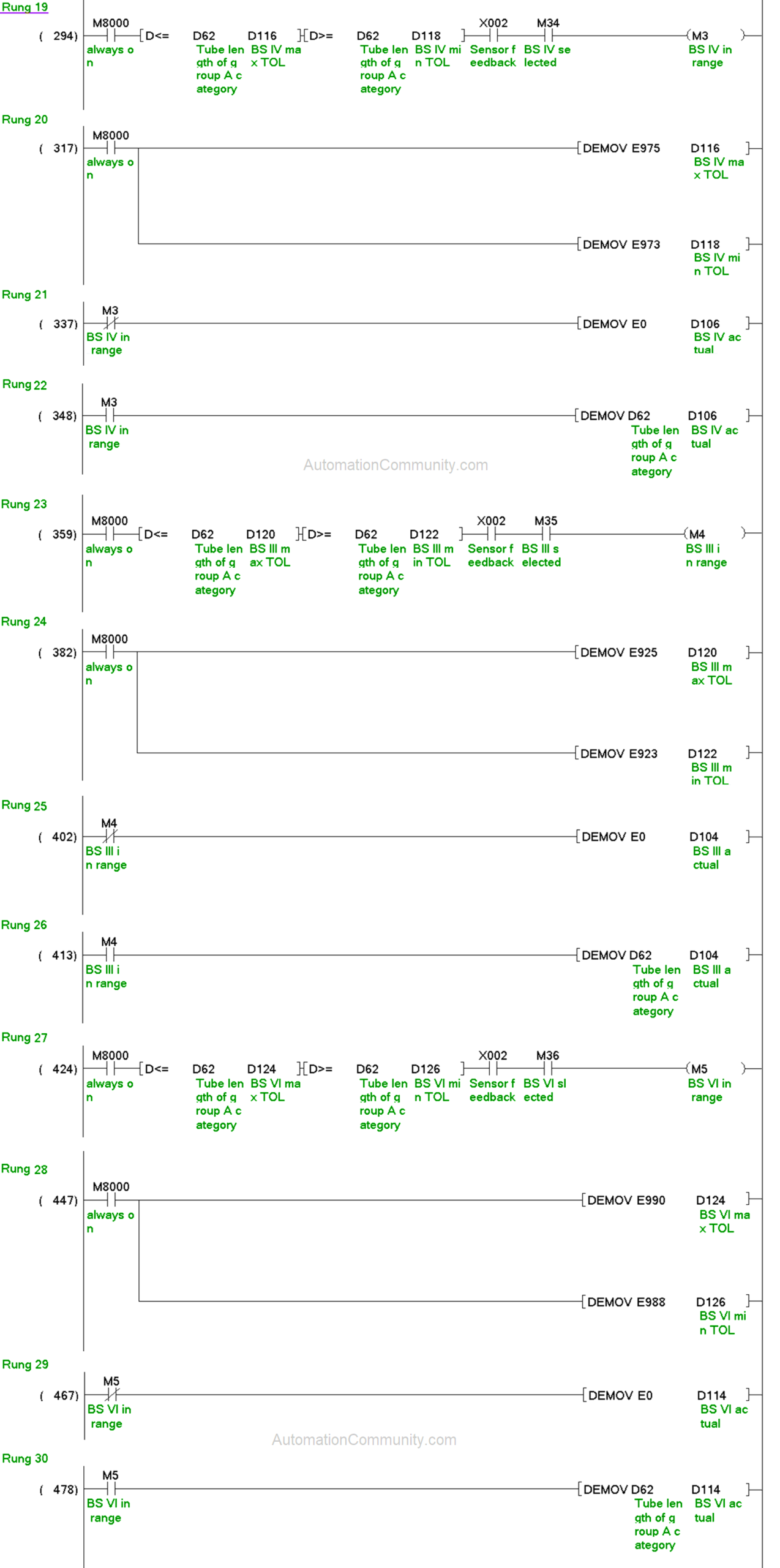
Rungs 19 to 30:
Similarly, all the other models of Group A are covered in rungs 19 to 30.
Rung 31 to 34:
D64 is equal to the “b” equated for group C. Mega of group C is covered in rungs 31 to 34. D128 and D130 hold the permissible range for this model through rung 32.
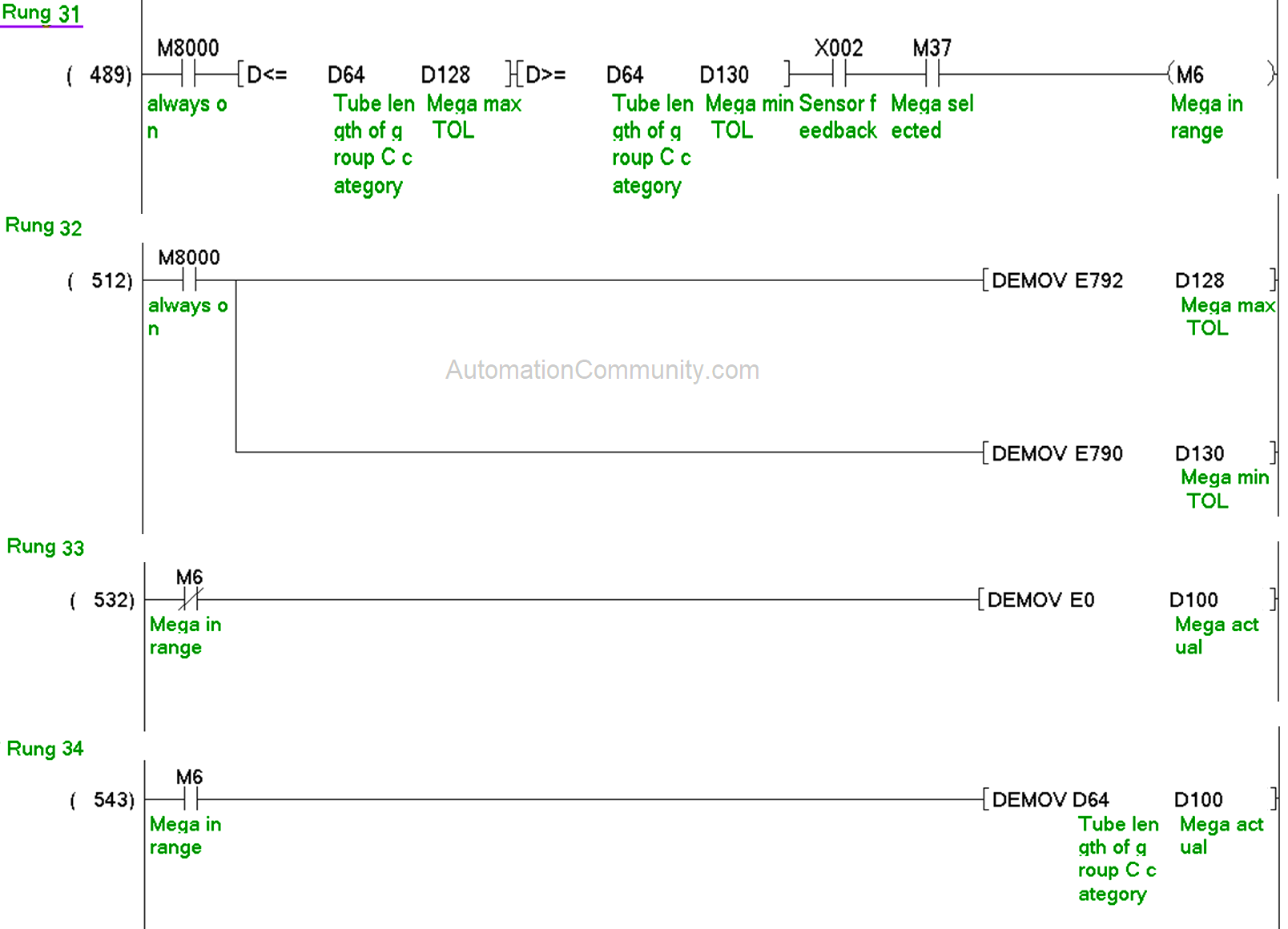
At the time of receiving the feedback sensor or when the mechanical fixture touches an end of the tube, the actuation of M6 in rung 31 shows that the actual length is in the permissible range which is displayed in HMI using D100 through rung 34.
If it is out of range, then D100 stays with the zero value through rung 33.
Rungs 35 to 42:
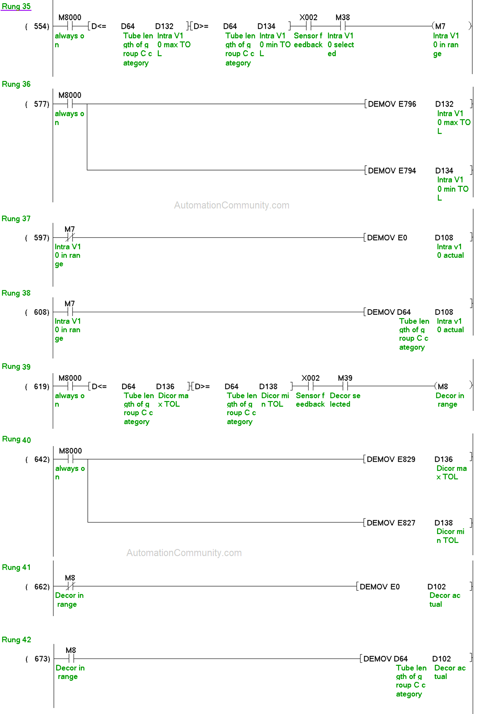
All the other models of the group C category are measured in rungs 35 to 42.
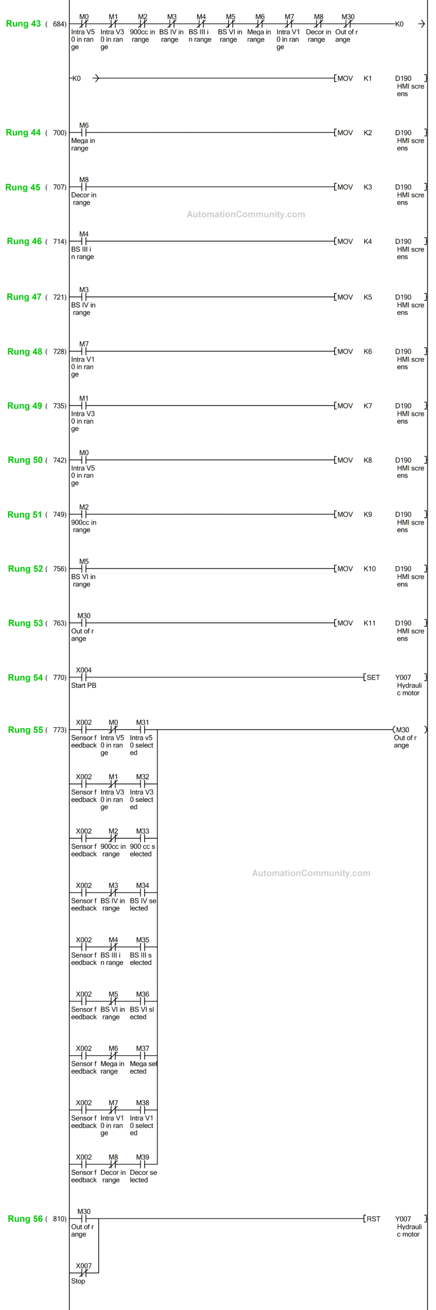
HMI Programming
The logic for model selection through HMI is shown below:
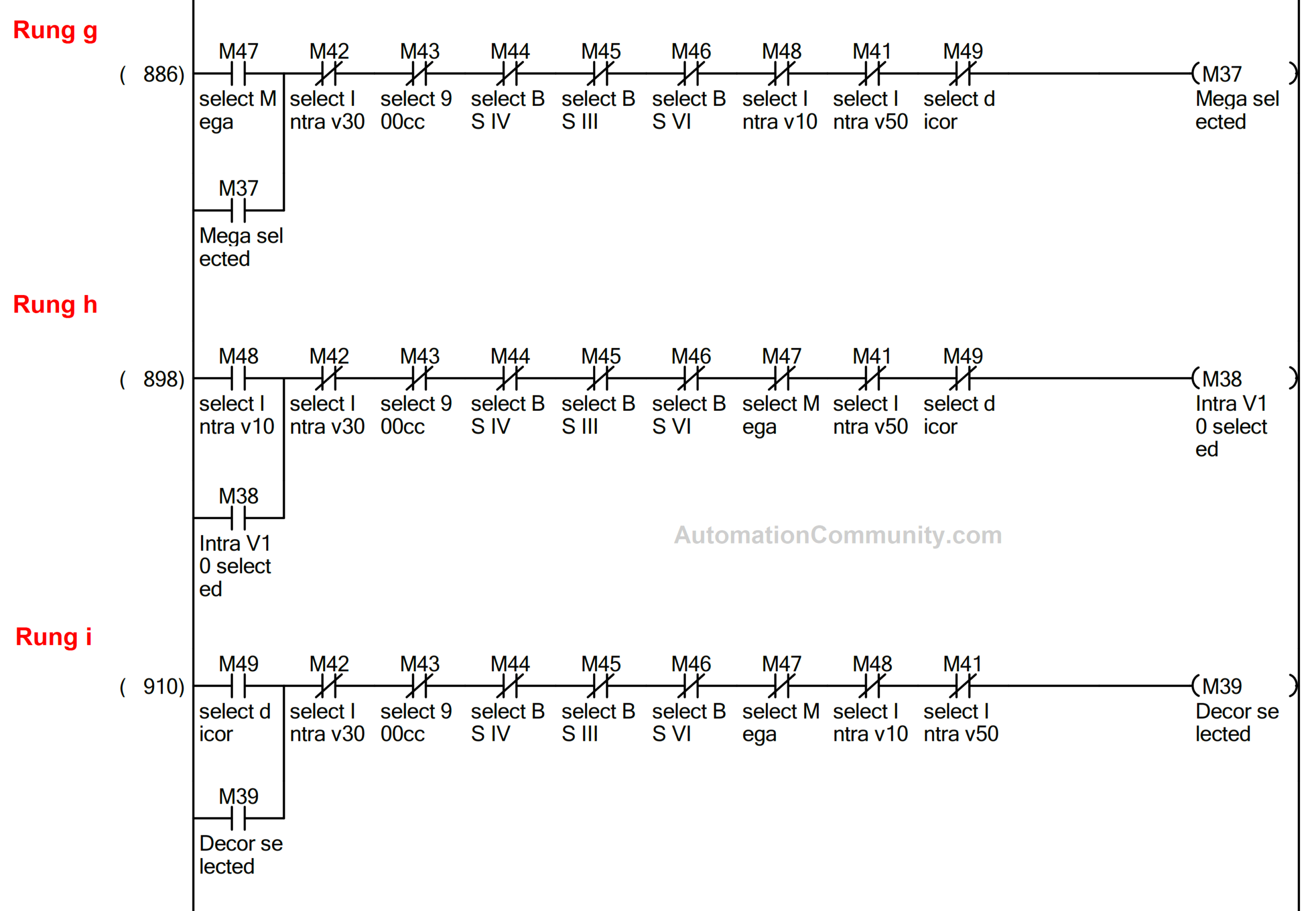
Rungs a to i:
M41 to M49 are the tags used for selecting different models in HMI. These are tagged in the momentary buttons used on the HMI screen for model selection.
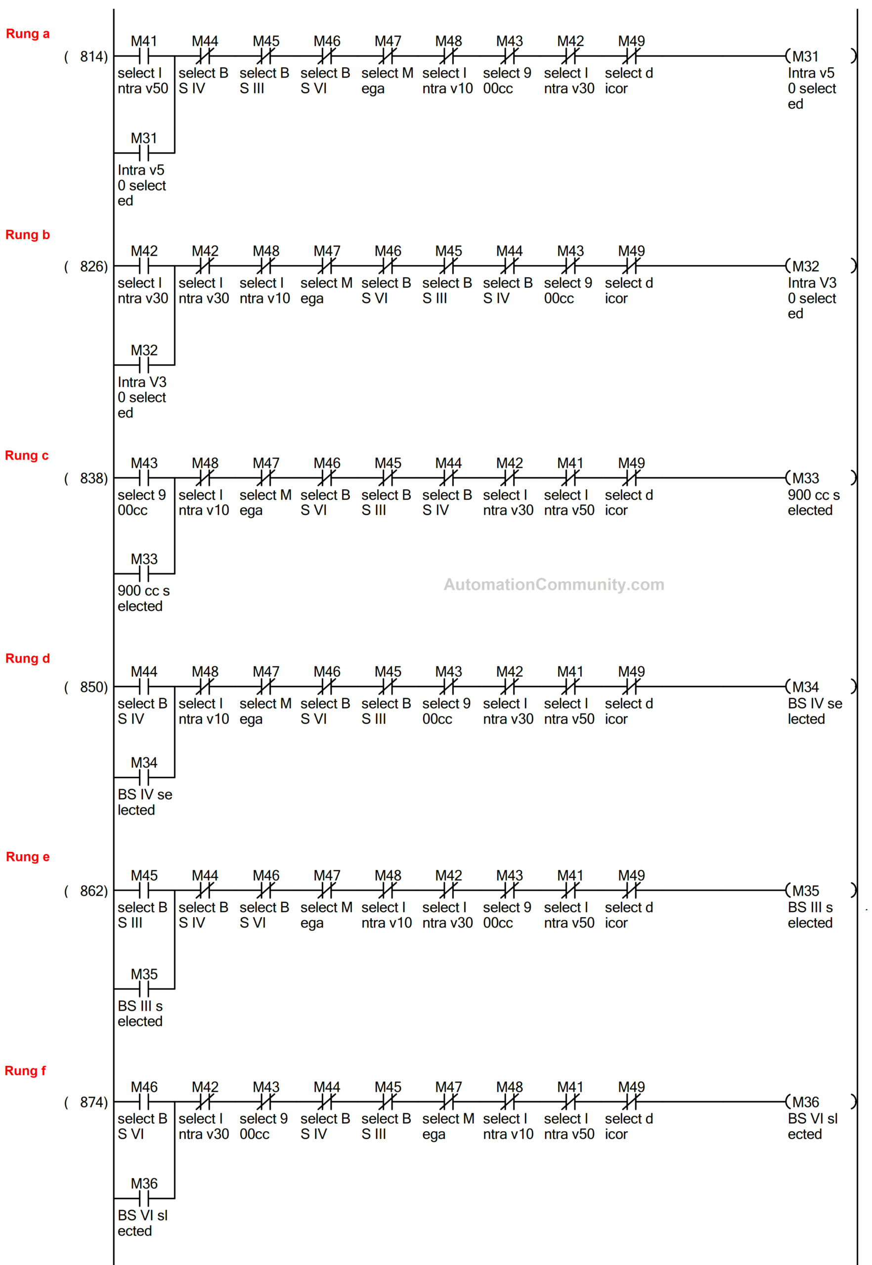
At a time, only one model could be selected as each button is interlocked by other buttons.
Whenever the length of the selected model is measured and it goes out of range, M30 is actuated in rung 55.
For example; While measuring Intra V10, if M7 is not actuated at the receiving of sensor feedback, then M30 is actuated which shows that the measured length is out of range.
Now, moving towards the logic for HMI screen switching.
Screen switching is done using data register D190.
Normally, when the core of LVDT is at the initial position or not at the one end of the tube i.e the movable fixture doesn’t touch an end of the tube, the first screen of HMI is displayed through rung 43 where the model selection is done.
The length of each tube is displayed on a different screen using screen-switching logic in rungs 44 to 52.
When the selected model length is detected as accepted through M0 to M8, the length is displayed on a specific screen defined for it.
Screens defined for the different models are as below:
| Model | Screen number |
| Mega | 2 |
| Décor | 3 |
| BS III | 4 |
| BS IV | 5 |
| Intra V 10 | 6 |
| Intra V 30 | 7 |
| Intra V50 | 8 |
| 900 CC | 9 |
| BS VI | 10 |
Apart from these, the screen no 11 pops up with text as “Out of range”, whenever the length of any tube goes out of range. It is switched through rung 53.
Rung 54 &56:
The hydraulic motor is on when the start PB is pressed and it is off when the stop PB is pressed or the length goes out of range (Poka-yoke introduction).
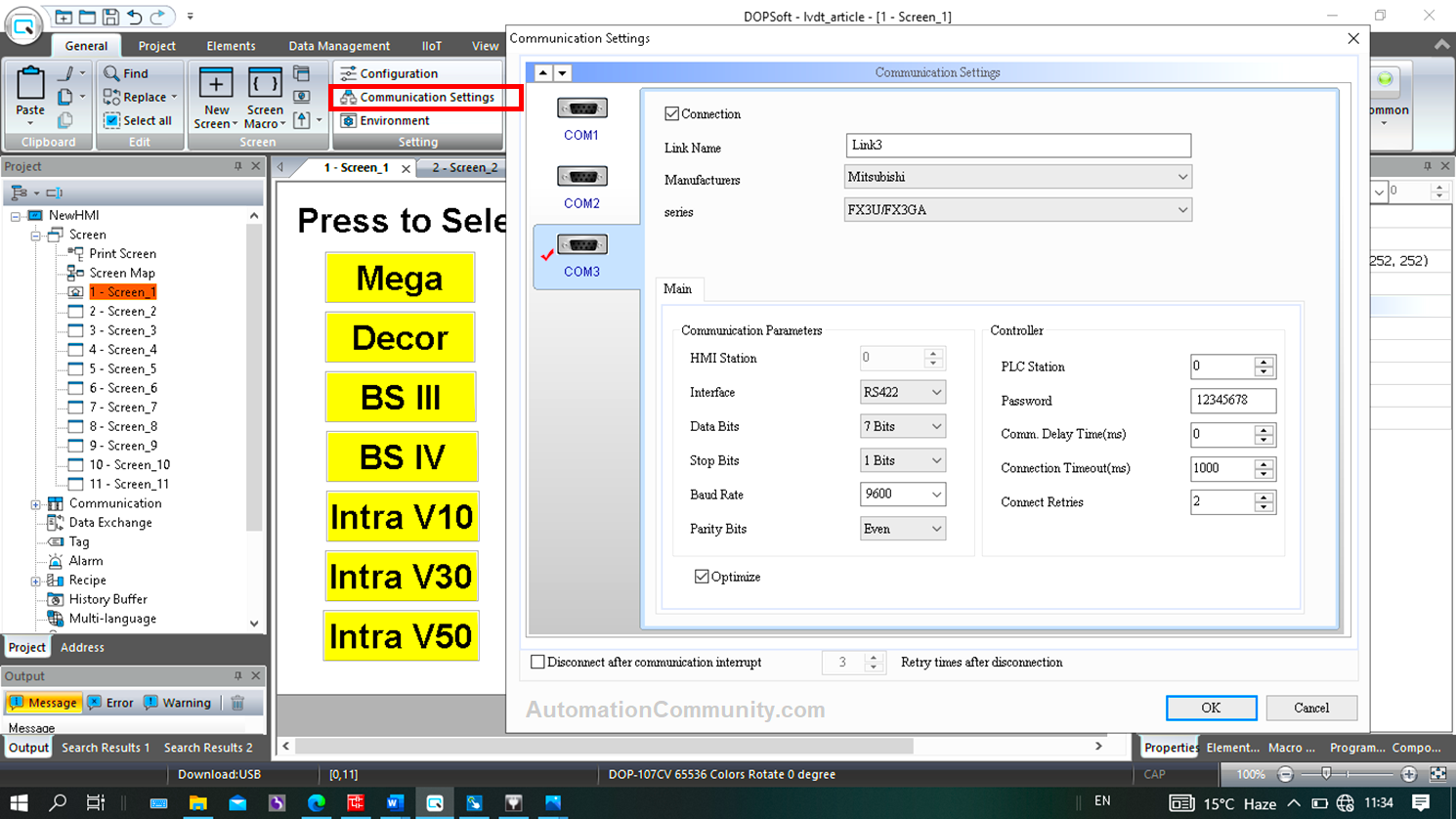
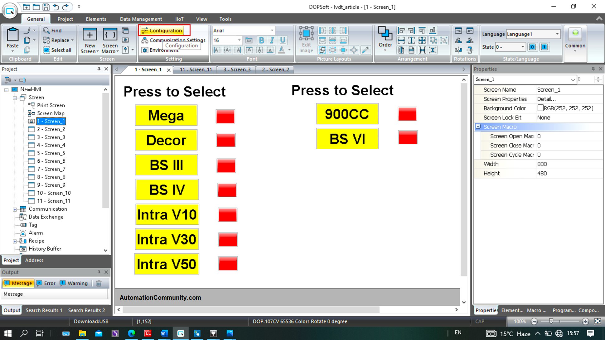
For configuring HMI, DOPSOFT V4.00.16 is used.
Feed the communication settings after clicking on the highlighted.
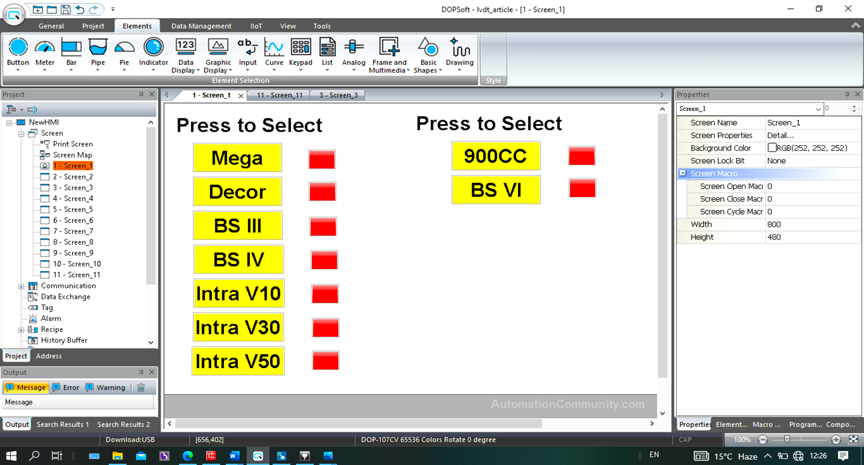
As per user requirements, a total of eleven screens are designed.
Each of the models has a designated screen for their length display, the details of which are described in the explanation of rungs 43 to 53 (see above).
Model selection is done on the first page.
The sample for designing a button for selection and its indication according to the PLC program is as below:
In the “Elements” section, click on “Button” followed by “Momentary”.
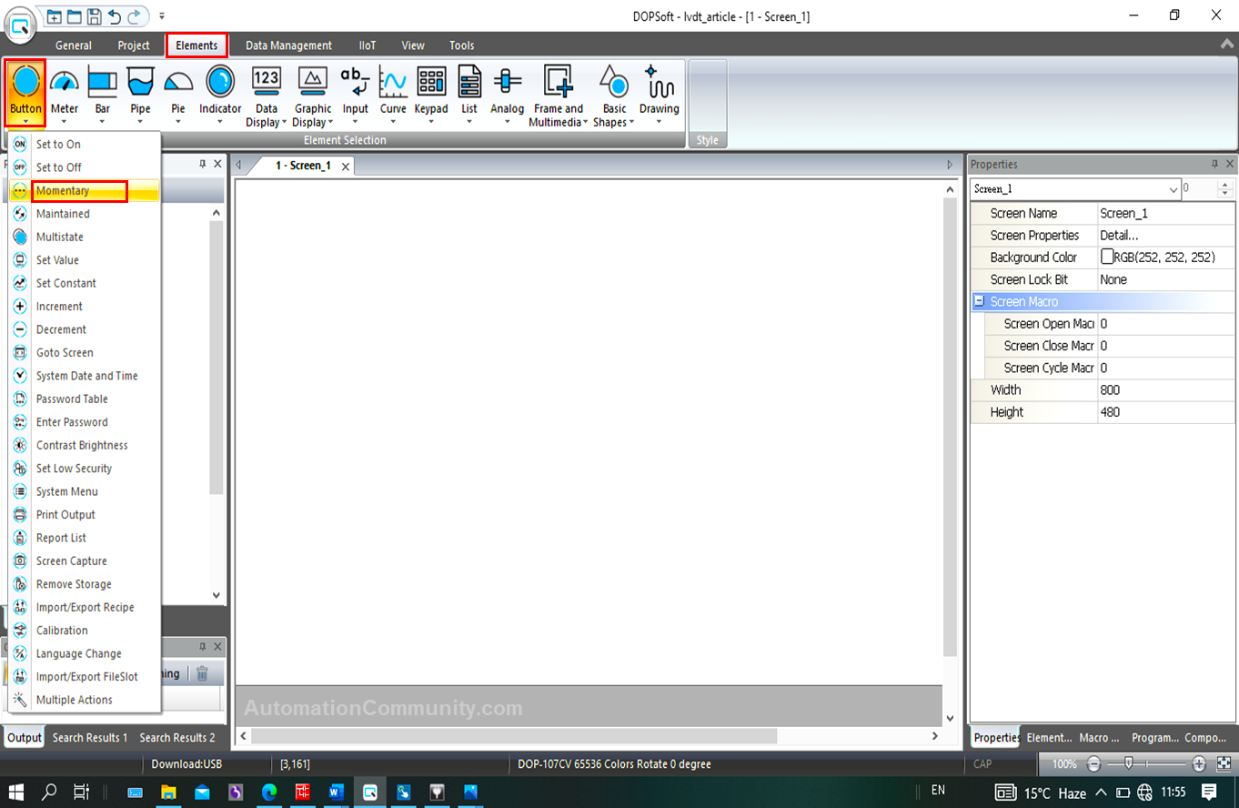
After dragging the button on the screen, tag the address in the write address section and feed the other settings as per need.
Here, this is the button used for selecting the Mega model, the corresponding bit for which is M47 (see rung “g”).
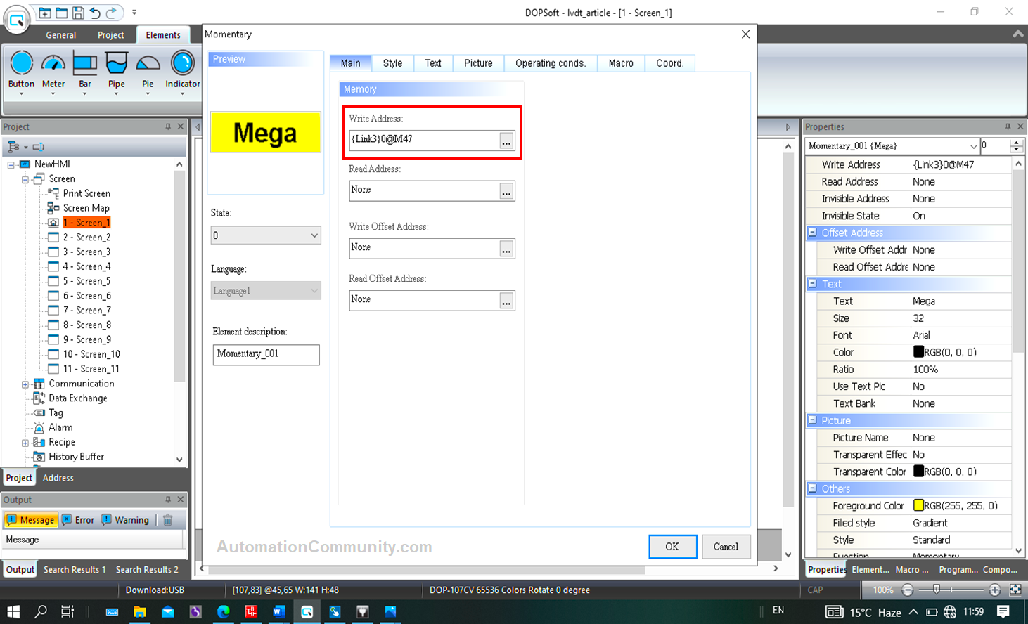
Similarly, for other model selections, see the corresponding bits used in rungs a to f, h, and i.
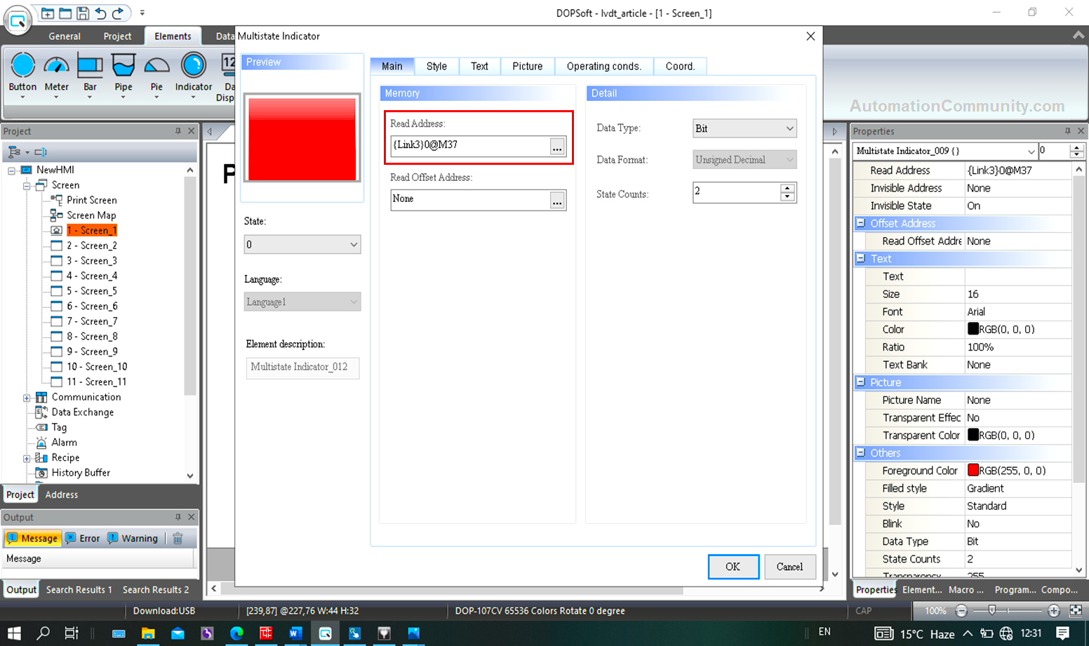
In the indicator section, click on the multistate indicator
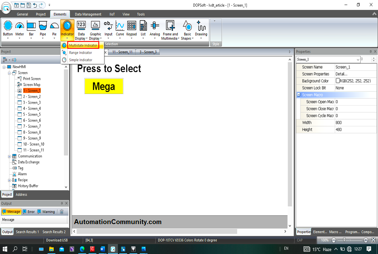
On dragging, the following pop-up window appears, where, for Mega model selection indication, M37 is tagged (see rung “g”). The NO contact of which is used in rungs 31 and 55.
When M37 is high, Green in state 1 indicates that “Mega” has been selected and Red in state 0 indicates that it has not been selected when M37 is low.
Similarly, other indicators should be tagged (see rungs a to f, h, and i)
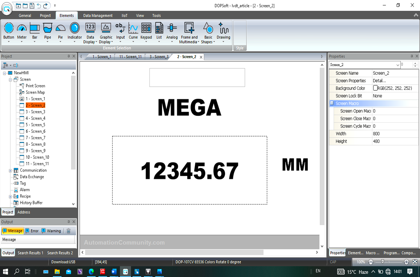
A sample of designing an individual screen for the length display of the “Mega” model is as below:
Screen 2 is used for the Mega model.
In the “Data Display” section, click on “Numeric Display”
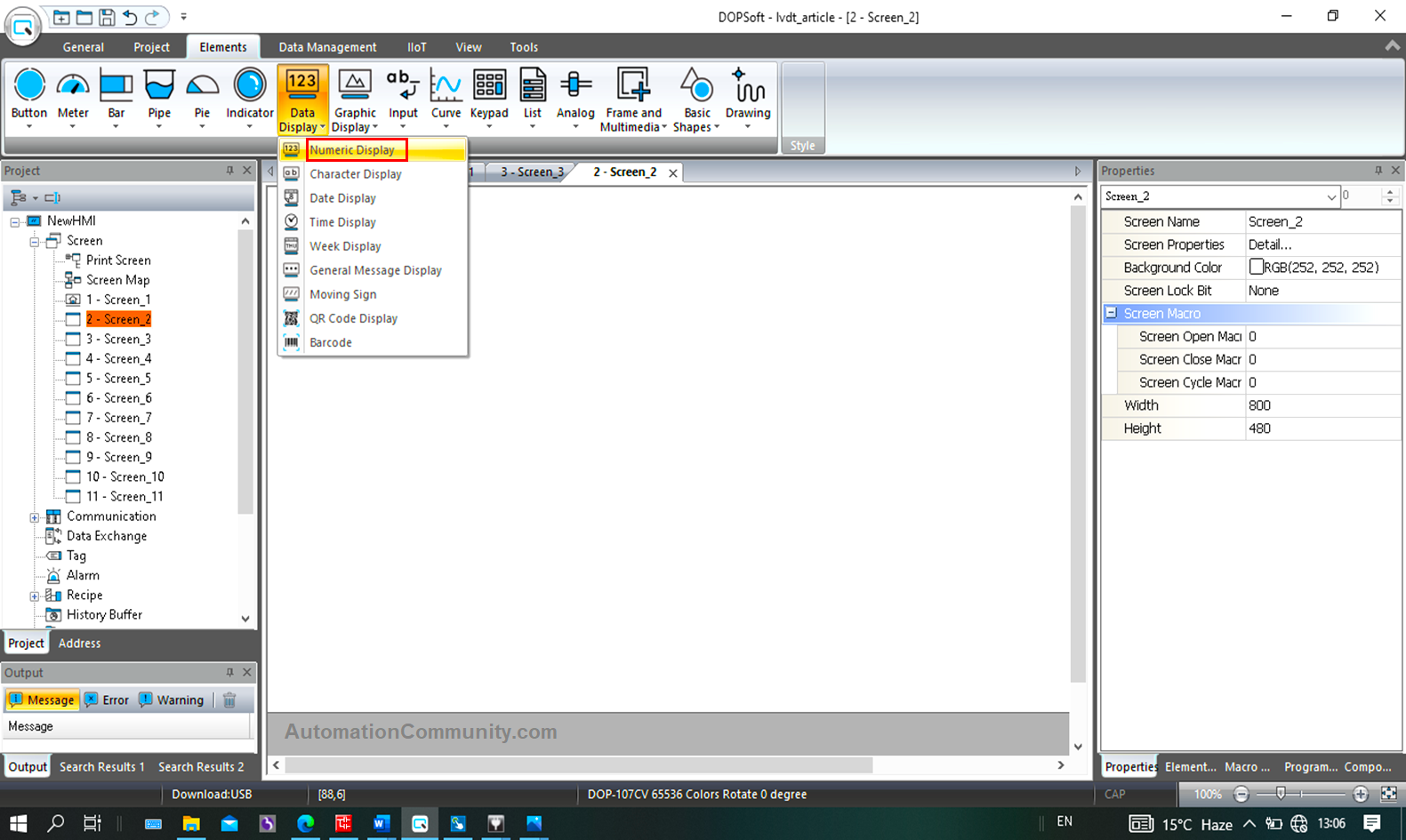
Drag and tag it as D100 (see rung 34) for the length display whenever it is in range.
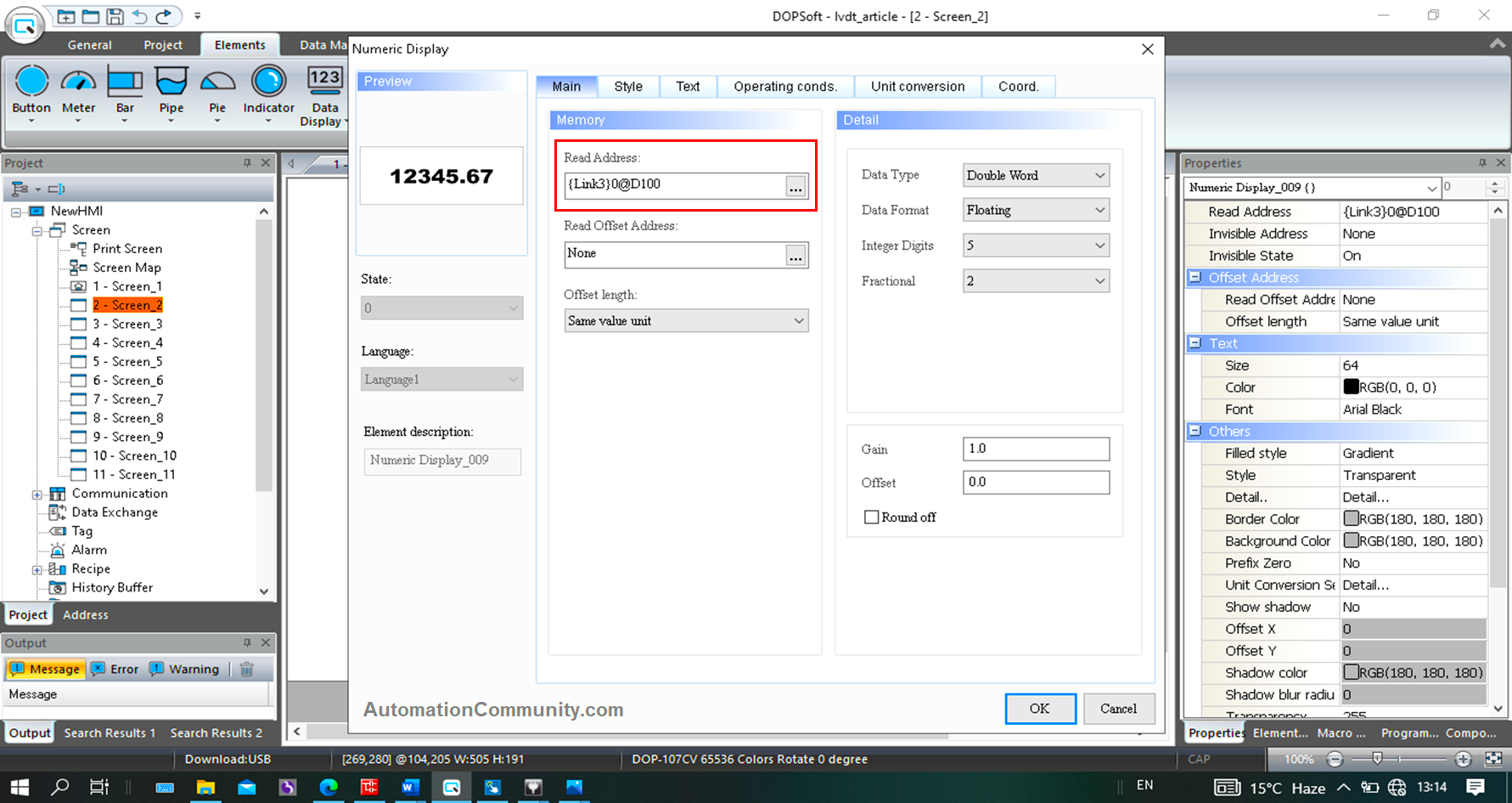
Specific memory bits are used which shows that the length is in range. These bits are tagged with the indicators on each screen.
Here, M6 is used for Mega display (see rung 31).
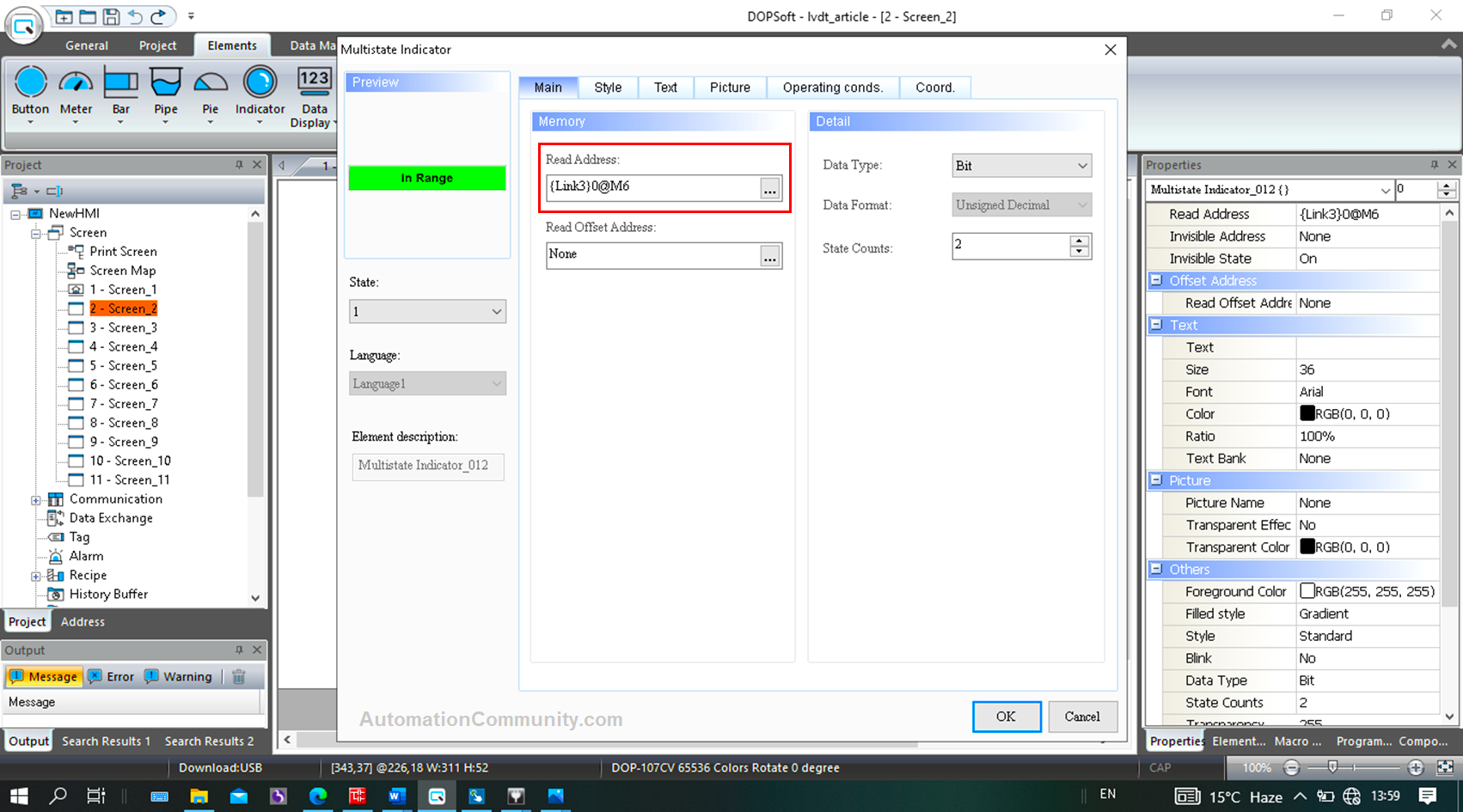
Highlighted block goes green with text as “In range”.
Similarly, other screens (3 to 10) can be designed. Study the logic implemented in Rung 7 to 42.
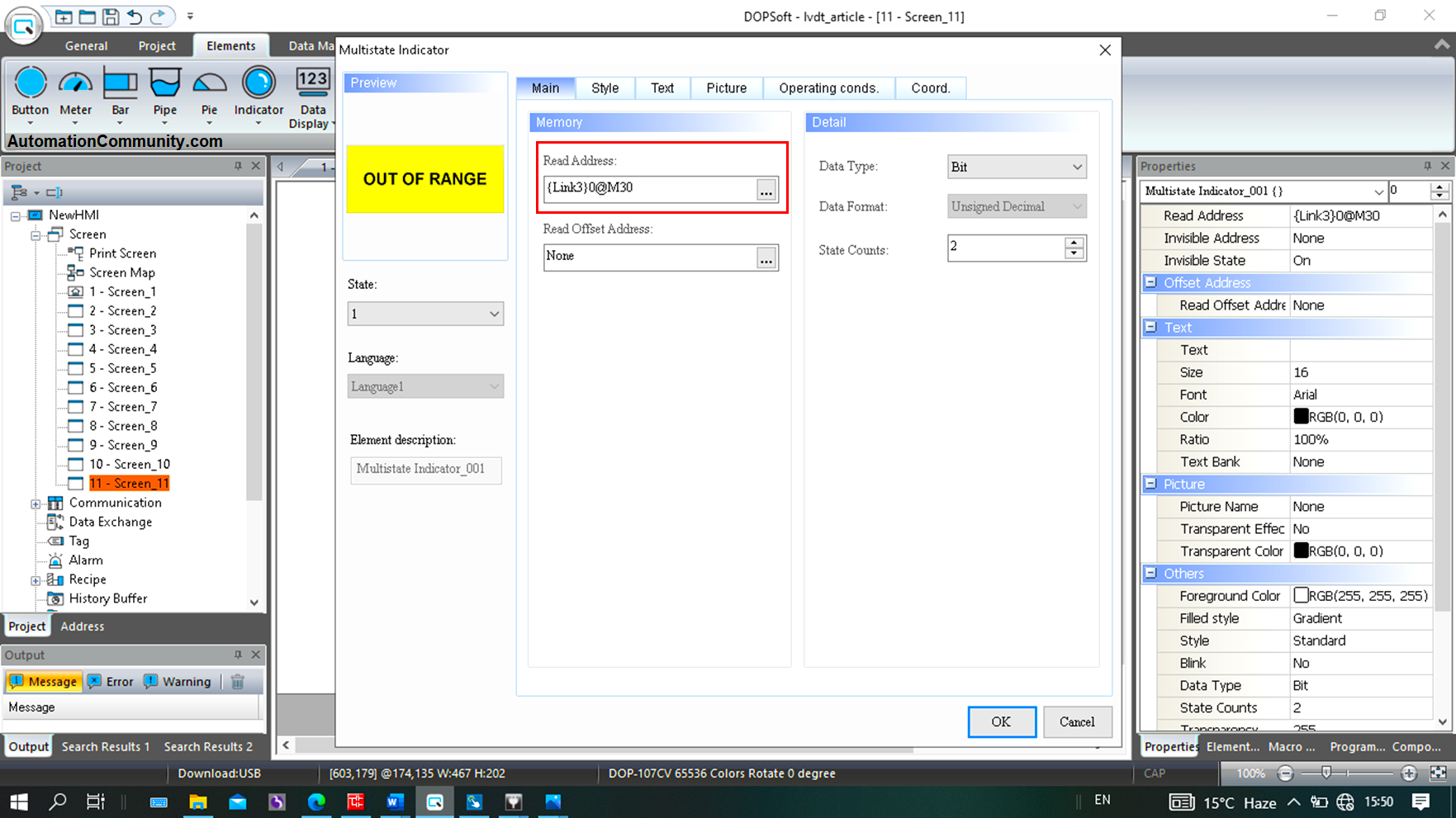
Similarly, when the measured length of any model goes out of range, screen no 11 pops up with a display as “Out of Range”.
M30 bit is used for “out of range” indication in the PLC logics in rung 55.
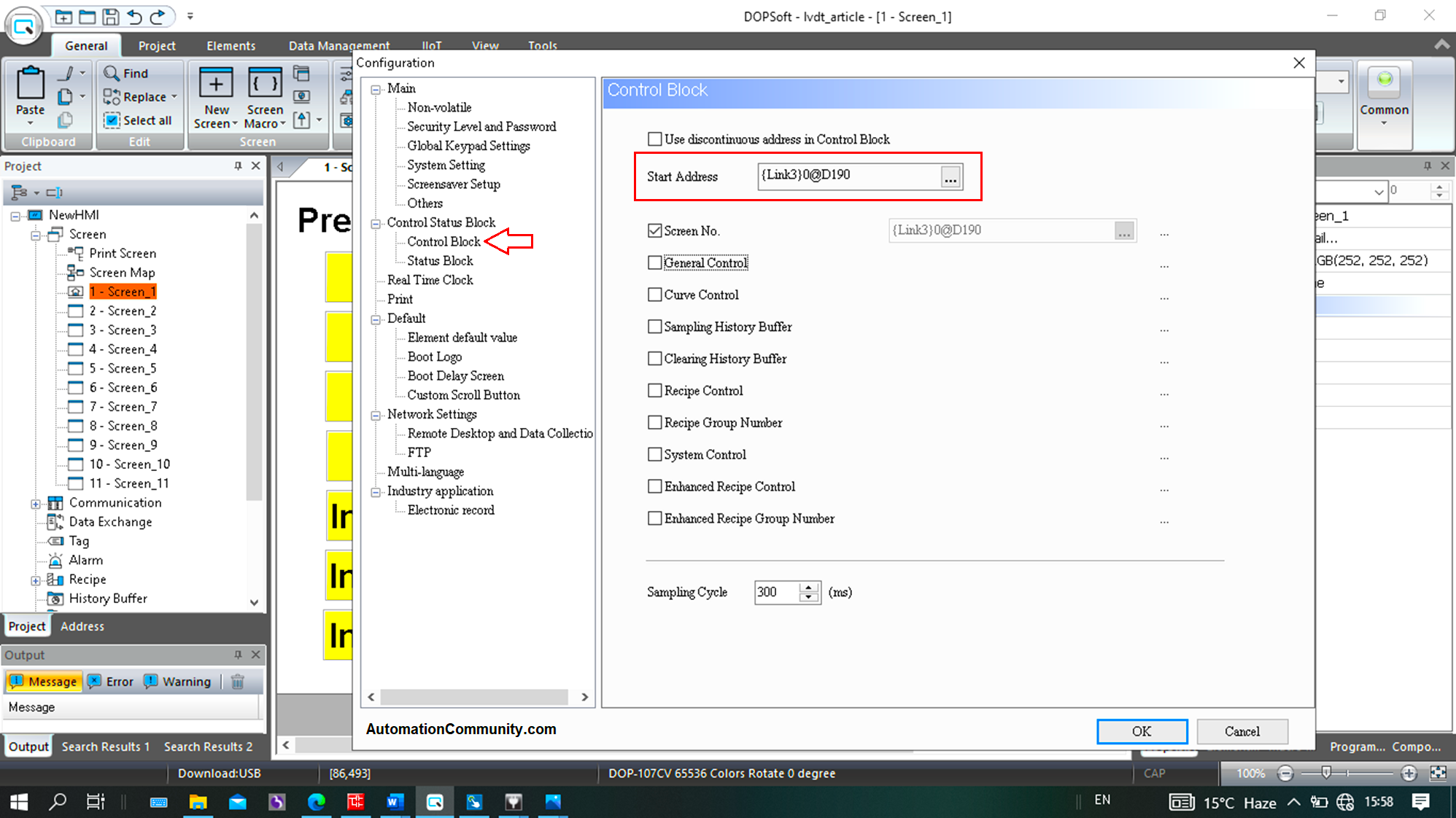
Now, screens need to be jumped automatically as per logic when a specific model has its length to display.
D190 is the data register used for screen switching through logic written in rungs 43 to 53.
Click on Configuration.
In the control block section, check screen No. block and feed the address as D190.
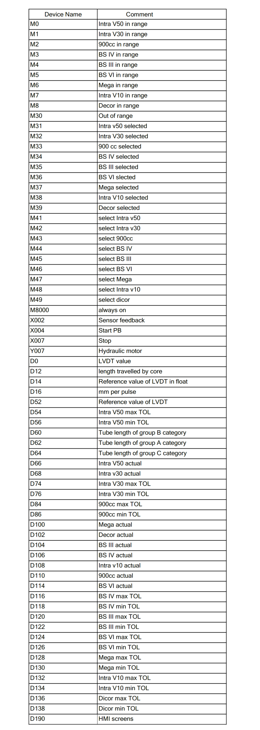
Devices List
The below table shows the list of devices or components used in this PLC project.
You download this PLC logic in PDF format and also the original source code of PLC and HMI logic.
In this way, the length of different tubes is measured using the PLC programming, LVDT, and HMI.
Read Next: