In this article, you will learn the PLC stepper motor control program for moving coil plate assemblies for a semi-automatic varnish machine.
PLC-based Semi-Automatic Varnish Machine
In this Special purpose machine (SPM) setup, a stepper motor is used to run the metallic bowl based on pulley and shaft assembly as shown in the below image.
The operation of this machine is briefly discussed. Here we focus on how to run the stepper motor with the PLC ladder logic for this machine operation.
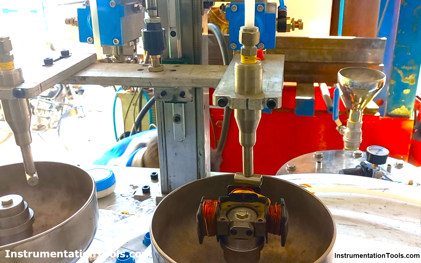
A three or four-pole coil plate assembly is placed over the Bowl shaft which rotates as the stepper motor rotates.
Metallic Bowl moves, such that each pole of a coil plate assembly is lubricated with the dispensing oil when moved by 90 degrees at each step.
This oil is dispensed from a pneumatic-based dispenser.
In this PLC project, we used Delta PLC DVP 16ES2 (Only Transistor type) and Delta HMI DOP 107 CV for this process.
Stepper Motor Driver Settings
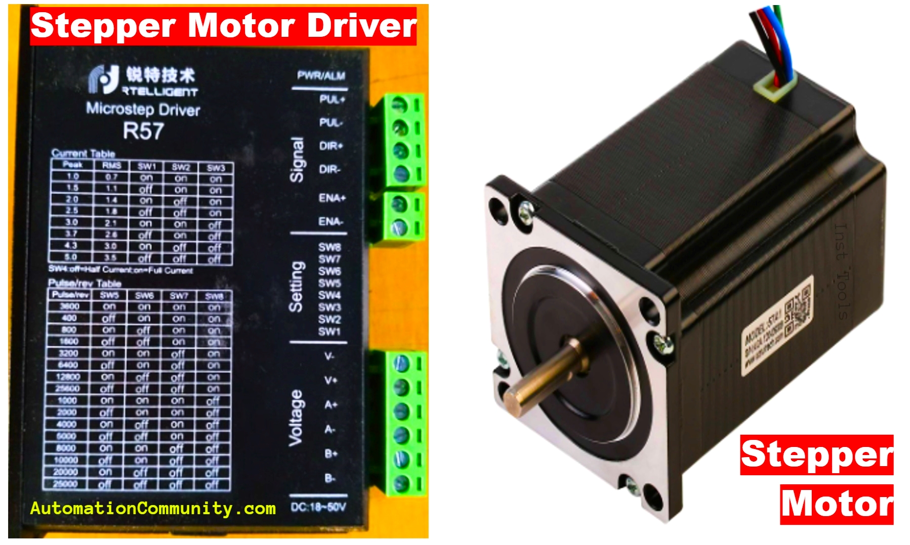
Here, the RTELLIGENT Stepper driver (R57) is used to run RTELLIGENT Steeper Motor (57A1-8) as shown in the below image.
High-speed outputs are required for controlling the Stepper motor through the Stepper drive.
DVP ES2 PLC allows only two channels as high pulse outputs, the details of which are shown below.
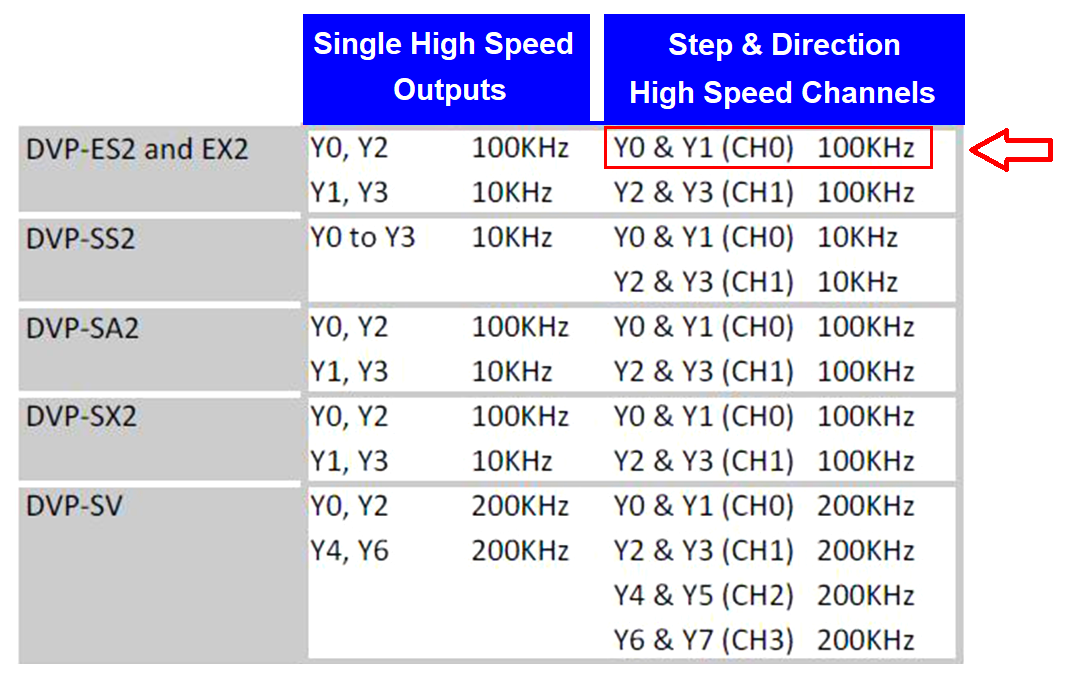
Here, channel CH0 is used as only one stepper motor is present in our machine.
In PLC, Y0 is used for pulse output and Y1 for direction reversing.
As the stepper motor has a rated current of 2.8 A, the current dip switch settings of the stepper driver are mentioned in the below image.
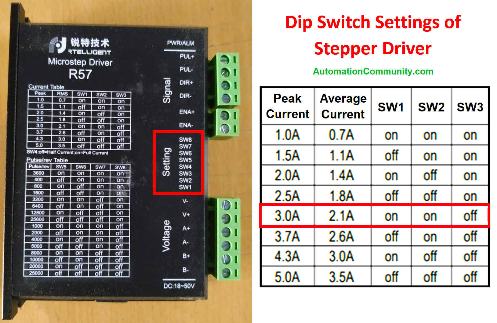
The stepper motor current may vary as per the heating conditions of the motor, but keep in mind the torque needs as well.
Half or the full current option for the stepper motor is decided by the DIP SW4 setting. Generally, it is set to off (Half Current mode) in order to reduce heating and improve reliability.
Wiring Details of PLC, Stepper Driver, and Stepper Motor
See the connection details of the Stepper driver with PLC and Stepper motor as shown in the below image.
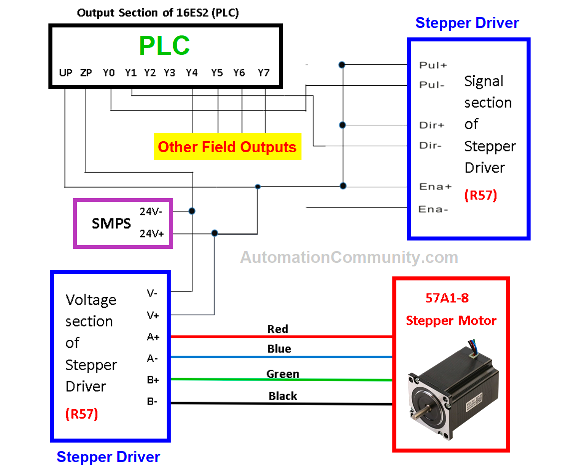
Here, the ENA port is not used (Set to disable by not connecting any wires to ENA-).
Disable condition ensures that the Motor is ready to move (the shaft is locked).
When it is enabled, the current supply to the motor is cut off and it will not respond to any pulses (the shaft is freely movable).
ENA port is also used to restart the driver after the rectification of any fault.
Pulses/revolution dip switch settings for this application are shown in the below image.
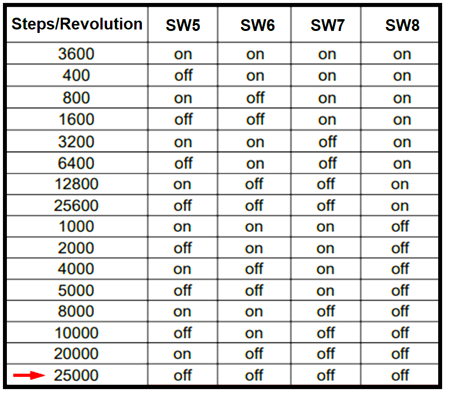
According to the settings, the stepper driver should receive 25000 pulses from PLC output Y0 to rotate the motor by one revolution.
A brief explanation of the process is described below.
Just look at the video below to get a brief understanding of the process.
The video includes the process for both three-pole and four-coil plate assemblies. But it does not include four pole assembly or a complete machine operation. The process for four-pole assembly can be understood after watching the video and reading the explanation below.
The video excludes oil dispensing and lubrication process but can easily understand after reading the below explanation.
Machine Operation
When the Start push button is pressed, a single-acting pneumatic cylinder moves down leading the mechanical arrangement of the dispenser to reach just above the pole winding.
Oil is dispensed from the dispenser for the defined time set in HMI.
During this duration of time, one of the winding poles is lubricated.
After completion of this time, the metallic Bowl moves by 90 degrees for the second pole to be lubricated.
This process is repeated until the third winding pole lubricates.
Now, as shown in the video, Bowl moves by 180 degrees after the third pole lubrication to reach its initial starting position.
As it completes the 360 degrees rotation, the cylinder is moved up to complete the cycle.
If the coil plate assembly has four poles, then the process is the same until the third pole reaches beneath the dispenser.
After the lubrication of the third winding pole, Bowl moves by 90 degrees instead of 180 as in the case of the three-pole assembly.
After the lubrication of the fourth winding pole, Bowl moves by 90 degrees completing the rotation of 360 degrees.
The cylinder now moves in an upward direction to complete the cycle.
PLC Logic
Now, moving towards PLC logic.
Look at the main IOs for this PLC program below:
- X6 as “Cylinder down reed switch”
- X5 as “Cylinder up reed switch”
- X2 as “Cycle start”
- Y6 as “Dispenser”
- Y0 as “move metallic bowl”
- Y5 as “cylinder”
The use of memory bits and data registers are explained in Ladder descriptions.
Rung 1
DPLSY is the instruction used as Pulse output for providing the pulses to the stepper drive through the designated channel output in PLC which is Y0.
The below instruction is used as shown in the below image.
DPLSY D474 D102 Y0
The speed of the motor is varied when the value in register D474 changes. D474 stores the frequency pulses.
Pulses (in integer) received in D102 defines the angle of rotation for the stepper motor according to the dip switch settings at the driver end.
Example: If 25000 pulses are set as pulse per revolution (PPR), then 6250 pulses are required for 90 degrees of movement.
When M200 is actuated, Bowl moves.
The condition for the actuation of the M200 is discussed later.
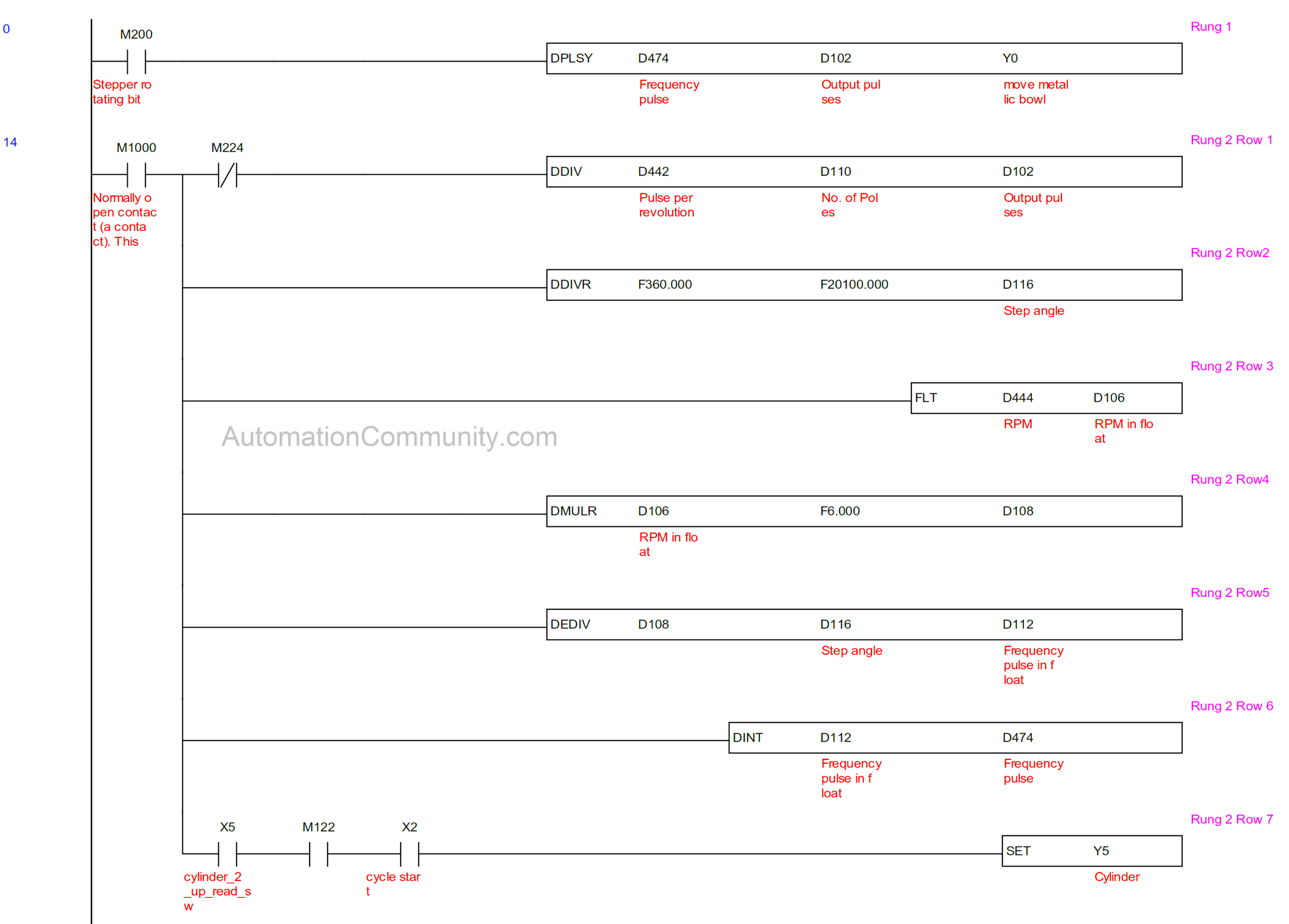
Rung 2 (Row 1 to 6)
As mentioned in Rung 1 description, there are two parameters for executing DPLSY instruction.
One is the Frequency pulse and the other is the output pulse.
We know the formula for stepper RPM as below:
RPM = [(Step angle * Frequency pulses * 60)]/360
or
Frequency pulses = (RPM * 6)/Step angle
Step angle = 360/ PPR
By physical analysis, it is found out that the pulley of Bowl’s shaft has a different diameter from the Stepper one, and both the pulleys are attached with a belt.
Using the Test Dial indicator, it was noted that 20100 pulses are required to rotate the metallic bowl by one revolution whereas the pulse per revolution (PPR) for the Stepper motor is 25000.
So, all the calculations are done according to this only.
Step angle = 360/20100 = 0.0179104478. This value is stored in D116 (see Row 2)
RPM is the variable quantity, the value of which is fed from HMI through D444 (integer) which is then converted into float and stored in D106 (see Row 3).
The frequency pulse is calculated in Rows 4 and 5 where D112 stores its value in float format. This is converted into Decimal and stored in D474(see Row 6).
The number of poles is fed from HMI through D110, which is divided by the Total pulses stored in D442 to give the exact number of pulses in D102 for rotating the bowl by the required angle (see Row 1).
Here, 20100 is permanently stored in D442 (Retentive) as a decimal value. So, if there are four number of poles, then D102 attains 5025 (Dec) to rotate the bowl by 90 degrees when M200 is actuated (see Rung 1).
The interlocking of M224 is discussed later.
When the upper position signal (X5) of the Cylinder is received, then Cylinder moves down through the actuation of Y5 if the cycle start button X2 is pressed (See Row 7).
If the number of poles fed is other than 3 or 4, then M122 is not actuated. Thus, the cylinder is not moved down or the cycle is not started. (See Rung 12)
Rung 3 and 4
As the lower position signal (X6) of the Cylinder is received through the reed switch, the oil dispensing process starts through the actuation of Y6. This is the stage where the first pole is lubricated. (See Rung 3 Row1).
At the same time, a 100ms on delay Timer T5 starts for the defined time as set in HMI through D454(See Rung 4 Row 1& 2).
If the coil plate assembly is of three poles, then the oil is dispensed three times.
If the coil plate assembly is of four poles, then the oil is dispensed four times.

The above two statements are executed through the comparison blocks including C0 (counter) in Rows 2,3 &4 of Rung 3. When C0 has a value equal to 1, Y6 is actuated the second time, and the second pole is lubricated. Same as for third and fourth pole lubrication.
Fourth pole lubrication is interlocked with M224, the actuation of which is discussed in Rung 12.
(Incrementing condition of counter C0 is discussed in Rung 6).
Rung 5, 6 and 7
In the 5th Rung, when timer T5 completes its time, M200 is set which fulfills the condition for rotating the metallic bowl and the metallic bowl is rotated (see Rung 1).
At the same time, Y6 is reset to stop the dispensing process.
When M200 is set, timer T5 (Non-retentive) loses its supply as well as Y6 can’t be set. (See Rung 3 & 4).
This ensures that Dispenser is on only for the defined time as set in HMI.
M1029 is a special internal bit for Channel 0, which gives a pulse when the stepper motor has rotated as per the defined pulses in DPLSY instruction.
Example: In DPLSY D474 D102 Y0, if 5025 pulses are required for 90 degrees rotation and D102 holds 5025(dec), then M1029 gives pulse after 90 degrees movement.
Read the two statements below:
(a) If the coil plate assembly is of 3 poles, then the bowl rotates in three steps to complete one revolution (90+90+180=360) (see video).
(b) If the coil plate assembly is of 4 poles, then the bowl rotates in four steps to complete one revolution (90+90+90+90=360) (Assume in the video)
In a cycle, when the bowl has rotated for the first time i.e. after completion of ninety degrees, counter C0
increments to 1(dec) and M200 is reset for the first time (see rung 6) to stop the bowl from rotating (see rung 1).
This is the condition when the second pole winding is beneath the dispenser for lubrication.
At the same time, Timer T5 restarts counting time as the contact of M200 goes NC. (See Rung 4)
Also, Y6 is set again to actuate the dispenser, and second pole lubrication is done (see Rung 3 row 2)
The process goes the same for the third pole lubrication.
The process value of C0 is equal to 2 when the third pole is beneath the dispenser.
(i) In the case of three pole assembly, after the Bowl moves by 180 degrees (refer to rungs 8, 9 & 10) just after the third pole lubrication reaches its initial position, done bit of C0 is activated (PV of C0=SV of C0=3) in rung 7 to move the cylinder upwards as Y5 is reset. Hence, the cycle is completed.
(ii) In the case of four pole assembly, after the Bowl moves by 90 degrees just after the fourth pole lubrication to reach its initial position, a done bit of C0 is activated (PV of C0=SV of C0=4) in rung 7 to move the cylinder upwards. Hence, the cycle is completed.
Note: Contact of M224 in Row 4 of Rung 3 remains NC only in case when four poles are selected in HMI (see rung 13).
Hence, Row 4 of Rung 3 is only valid for four pole assemblies.
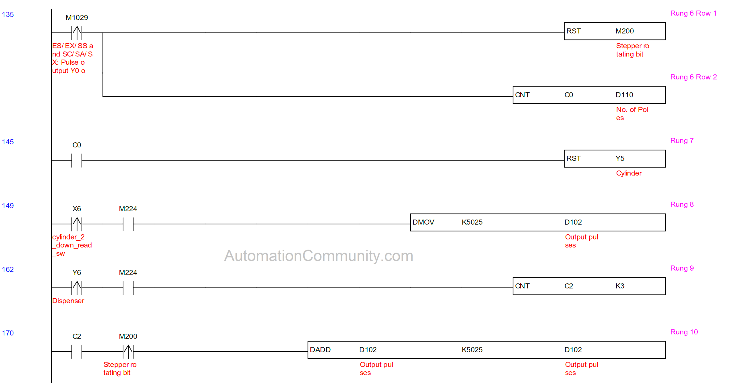
Rung 8, 9, 10 and 11
As discussed above, there is a difference in the movement angle of the Bowl after the third pole lubrication for four and three-pole assembly.
For four poles, the rotational angle is equally distributed in 4 steps i.e. 90 degrees in each step. For this, separate logic is not needed as D102 holds the stable value of 5025(dec) (See Row 1 of Rung 2)
For three poles, the rotational angle is distributed in 3 steps i.e. 90, 90 & 180 degrees in respective steps.
When three poles are selected in HMI (refer to rung 13), the calculation of pulses in row 1 of rung 2 becomes invalid as the closed contact of M224 opens.
Initially, when the down position feedback of the “up/down cylinder” is received through X6 as a rising edge, 5025(dec) is moved in D102 for the Bowl to move 90 degrees in the first two steps (see Rung 8).
It is to be noted that the dispenser actuates three times in a cycle. A counter C2 of set value 3, is incremented every time the dispenser actuates. (See Rung 9)
The lubrication process of the third pole indicates that the dispenser has been actuated three times yet. Thus, a done bit of C2 is activated in Rung 10.
When the dispensing process stops, M200 is actuated to move the Bowl further. At this time only, 5025(dec) is added to the existing value of D102 which was 5025(dec) (See Rung 10).
The new value is 1050 (Dec). Hence, Bowl moves with 180 degrees of rotation.
After the upward movement of the cylinder, the signal of the up-reed switch (X5) is used to reset C2 and C0. (See Rung 11).
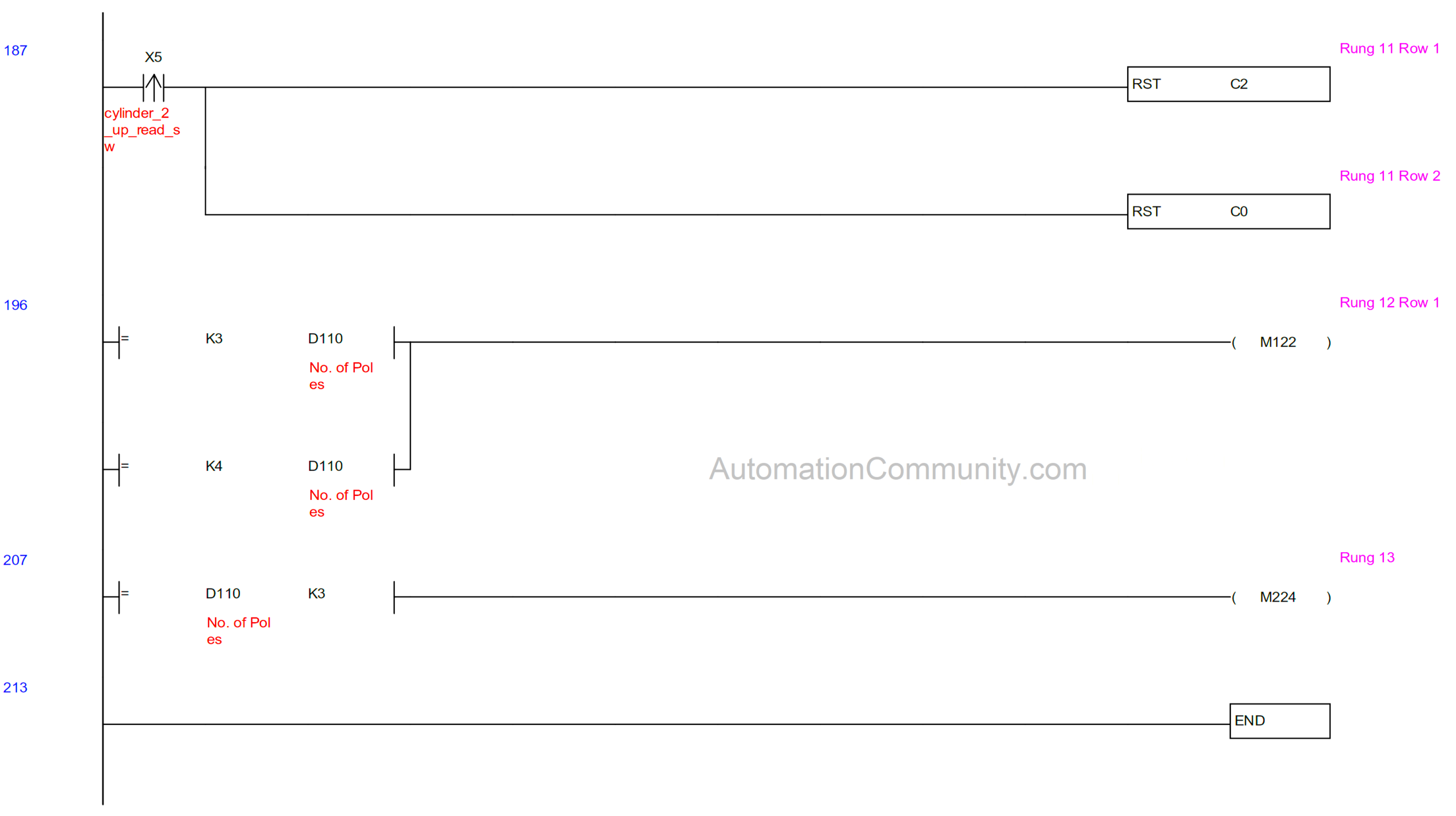
Rung 12 & 13
M122 is actuated as a result of the selection of three or four poles from HMI. The cycle will only start if it is actuated (See Rung 2 Row 7).
When the number of poles selected in HMI is three, M224 is actuated (See Rung 13), the interlocking of which is used in rungs 2,3,8 & 9 (Already described).
You can download the Stepper Motor PLC Logic in PDF format.
HMI Details
HMI to PLC connection details is as below:
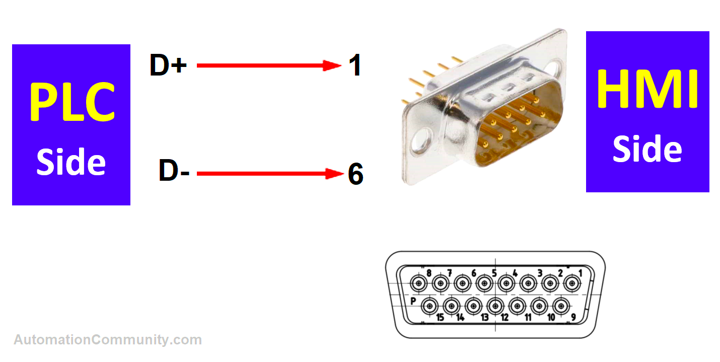
The above connection is as per the RS485 protocol. Here we used COM Port 2.
Here in this article, HMI programming is discussed in brief only.
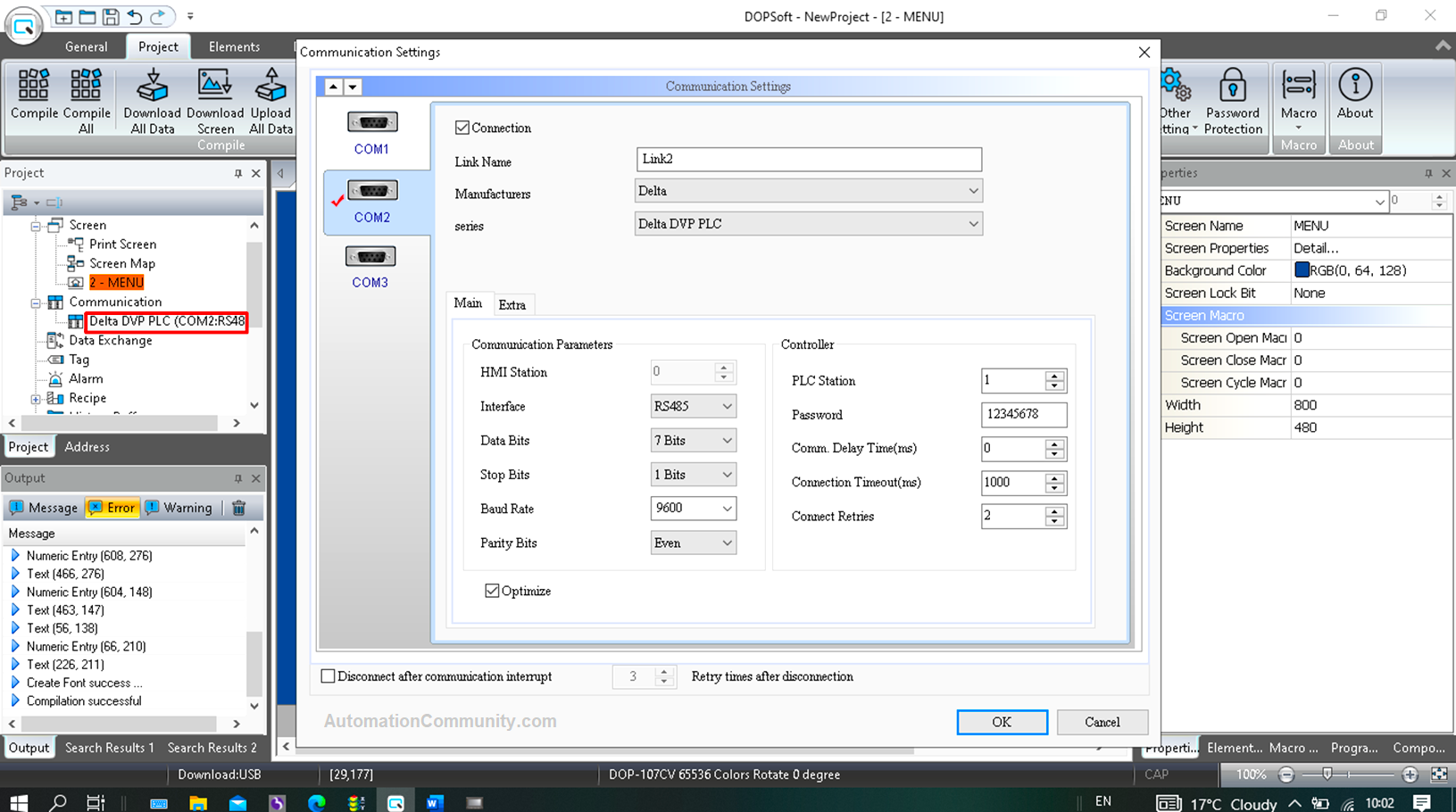
To configure it in HMI, Open DOP soft V4.00.16 and feed the settings as shown below after clicking on “Communication”
- Three variable data to be fed from HMI are
- “Dispenser actuating time” tagged as D454
- “Pole setting” for coil plate assembly tagged as D110
- Stepper Motor’s “RPM” setting is tagged as D444.
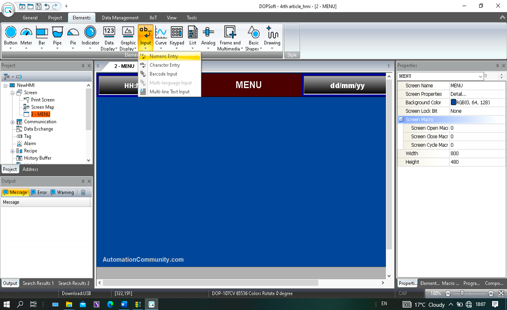
To configure the above, three numeric inputs are taken on the HMI screen. The configuration of one is below.
In the “Elements” section, go to “Input” followed by “numeric entry”.
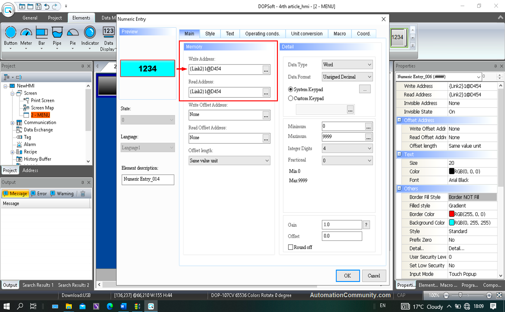
Double-click the dragged button and tag the address in the highlighted section.
Here, the address for Dispenser actuating time is tagged as D454. (See PLC program description)
Similarly, take the other two numeric inputs too.
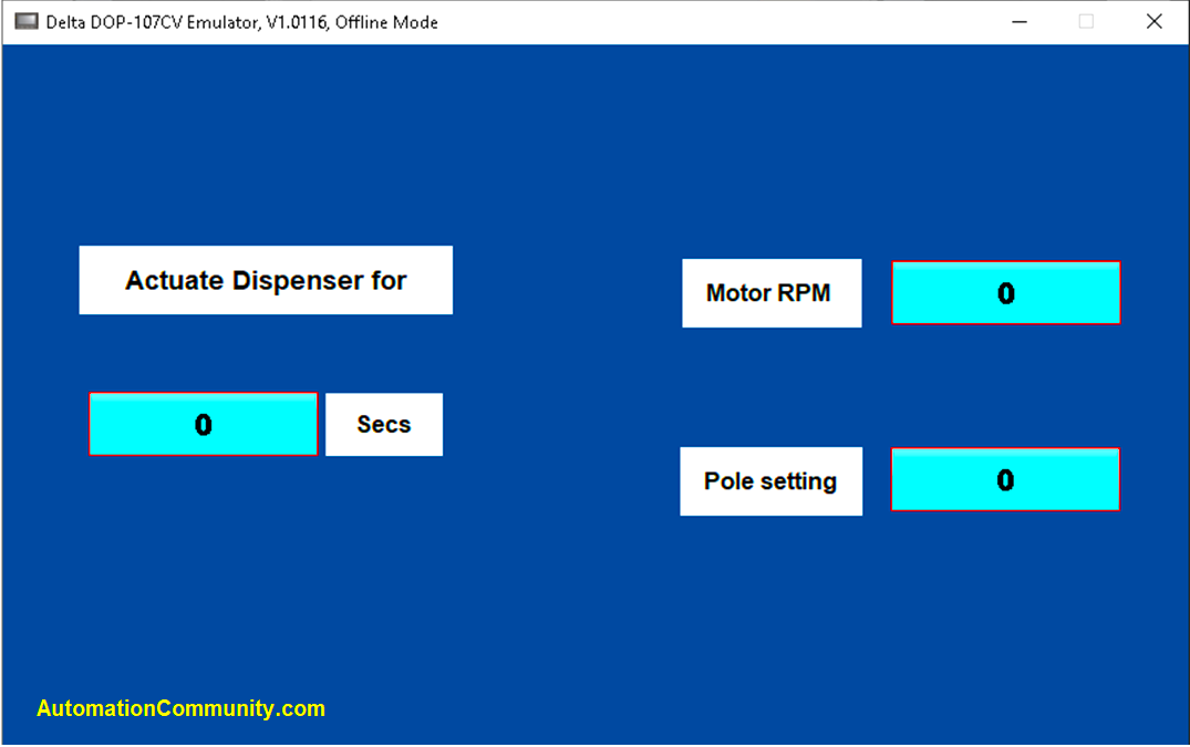
The HMI final Screen is shown above.
In this way, the stepper motor can be controlled for a particular application using programmable logic controllers.
Read Next: