RS in 232, 422, and 485 denotes Recommended Standard used for serial data communication (data transfer) developed by Electronic Industry Association (EIA).
Developed in the 1960s, computer communication standards experienced their popularity with the development of computers, such as links between computers minicomputers, and terminals.
Recommended Standard (RS) was used for industrial computing until it reached the world of PCs, which included the famous “COM” ports.
Despite being with its outdated performance by the introduction of USB buses and Ethernet links, Recommended Standard (RS) is still used in proprietary systems.
Even if the laptops or office personnel computers no longer have COM interfaces with 9-pin or 25-pin sub-D sockets, industrial PCs offer them and there are USB to RS232 or RS 422/485 converter interfaces.
Many segments of equipment for computer control applications: measuring instruments, PLCs, PCs, and network servers, still used these interfaces.
RS 232
The RS-232 standard supports serial, asynchronous, and duplex communication between two devices. RS232 is a byte-based communication rather than a bit-based one.
As the most popular serial communication protocol, it is widely used. The RS232 serial port is present on most Windows PCs. RS232 allows only one master and one slave to communicate on each line. RS232 operates in a full duplex mode, and its communication speed reaches up to 115Kbilts/s.
In RS-232, the distance between the two devices does not generally exceed 15 meters (50 ft). That means RS232 is limited to shorter run lengths.
Speed and distance of RS 232 Standard
The standard RS-232 defines standard communication speeds from 2400 to 115200 baud, even if other speeds exist (75 baud/1200 baud as on the minutes).
The maximum communication distances depend of course on the chosen speed and culminate at 60m at 2400 baud
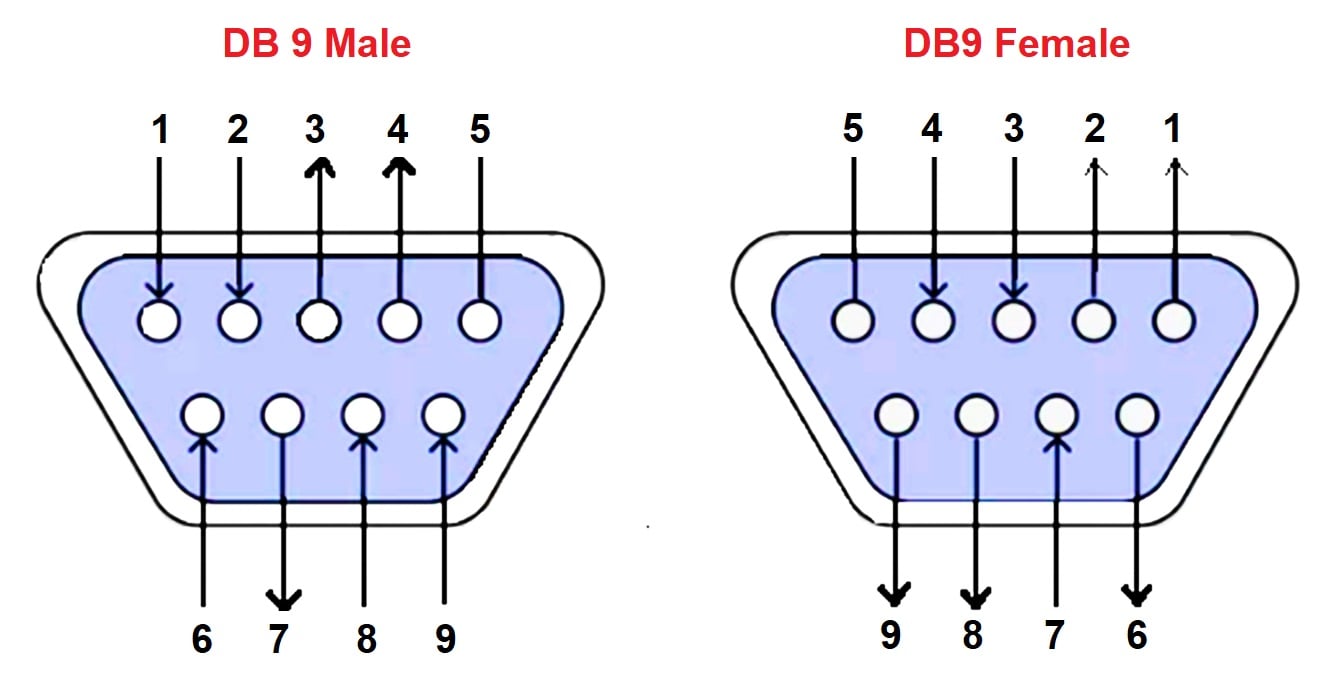
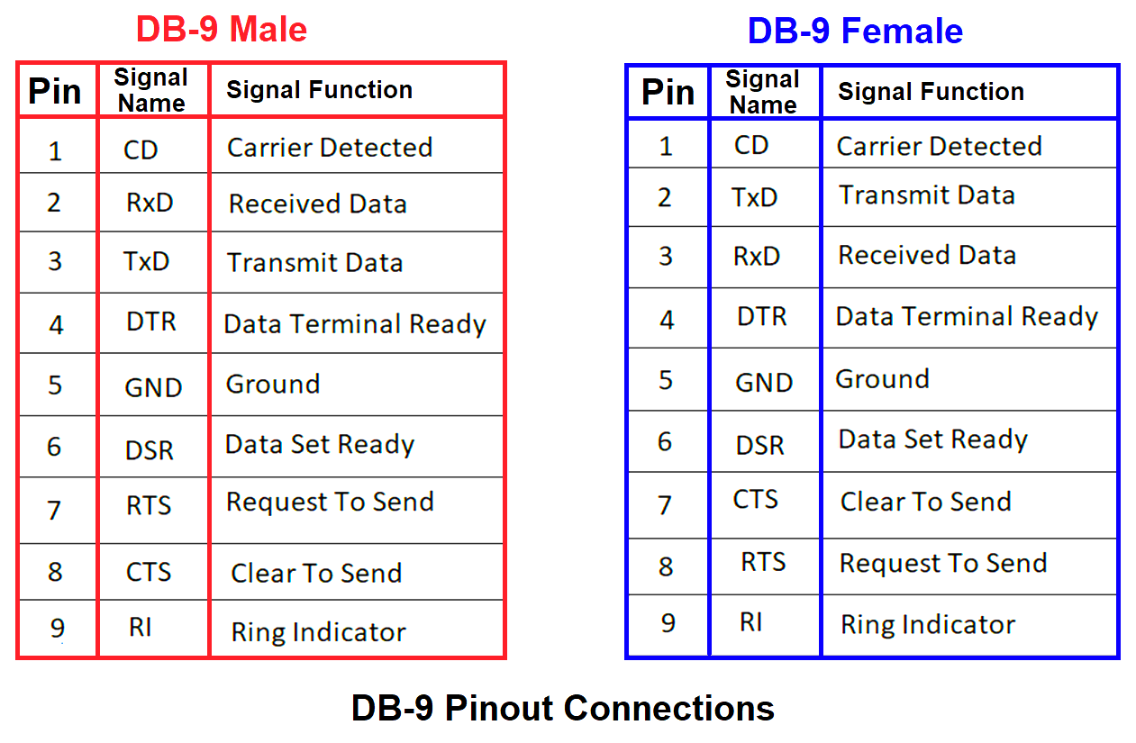
Connectors-DB9 RS-232 Pinout
RS-232 uses two transmission lines: RxD and TxD (Receive and data transmission). In addition, the standard defines two roles: DTE (Data Terminal Equipment) – the PC for example.
Whereas DCE (Data Communication Equipment), is originally modern.
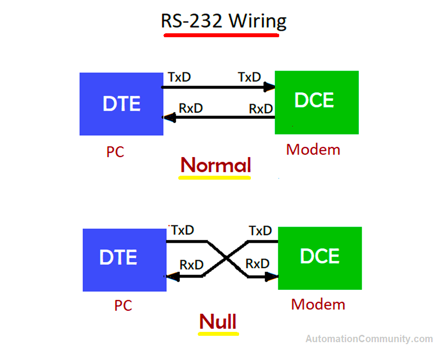
Accordingly, the DTE sends the data over TxD and receives it over RxD. With the reverse for the DCE. When two DTEs are interconnected, a “null modem” cable is used for which the TxD and RxD wires are crossed.
The Rs-232 connection is of Type DE-9, 9 pins (Equivalent DB-9) or DB-25, 25 pins.
Other pins are defined, for example for synchronization of exchanges (CTS/DTR and DSR/DTR).
Synchronization of exchanges
Some (old) equipment has communication buffers that are too small concerning the data rate. They can lose data if they are saturated.
A synchronization of exchanges (handshake) solves the problem. It is possible in two forms:
Hardware
The use of CTS/DTS lines. This technique weighs down the cables with 2 additional wires.
Software
Sending special characters back: Xon (Ctrl-Q) and X-off (Ctrl-S).
Protocol
To establish an RS-232 link, one must first ensure that the two devices share the same asynchronous speed.
Electrical Levels
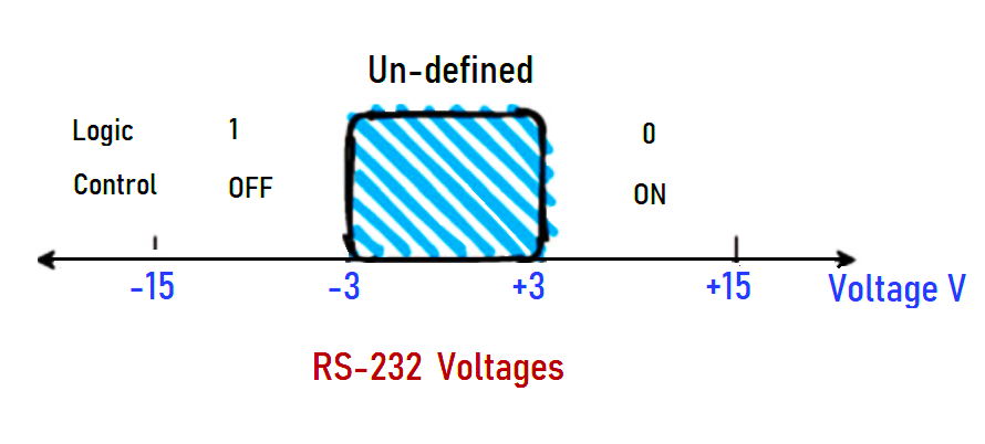
A logical “zero” corresponds to a voltage between +3 volts to +15 volts and a “1” to a voltage between -3 V to -15 V.
In between the range -3V and +3 V is undefined in the standard, and the data is considered invalid.
Uses
RS-232 port is widely used for connecting modems, printers, and other peripheral devices with PCs. RS232 is used in several lab and commercial devices such as LED displays, Barcode scanners, check weights, and scales.
RS-422
The Electronic Industries Association (EIA) has approved RS-422 as a serial communication standard.
RS-422 Cabling
The RS-422 standard is an evolution of the RS-232. RS422 is specified as a simplex multidrop standard, which means that in addition to communicating between two devices, the RS-422 allows a device to send messages to up to 10 receivers.
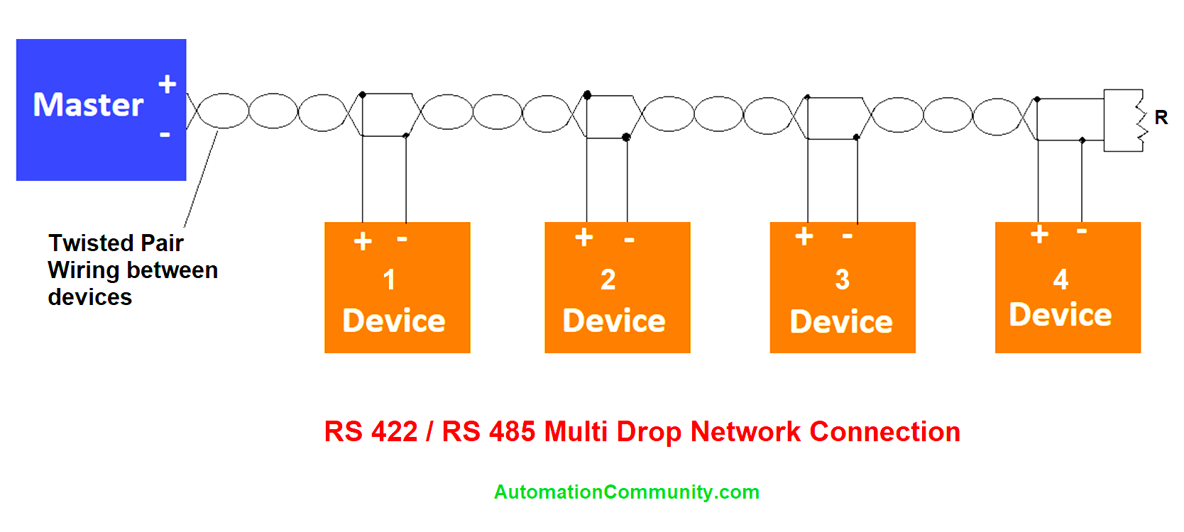
The physical medium defined for RS-422 consists of two twisted pairs, one of which is used for transmitter communication (usually the master) to the receivers (generally the slaves), the other being used for the communication of the slaves with the master.
Since several slaves must transmit on the same pair of wires, they must switch their transmitters so that only one transmitter is active at a time. The use of two pairs allows the transmission and receiving of data between the master and a slave at the same time. The possibility of transmission and reception of simultaneous signals characterize the RS-422 in full-duplex.
RS-422 standard was introduced to allow data transfer over serial data lines at a higher rate than possible with RS-232.
The primary reason RS-422 can achieve these improved results is the use of differential or balanced transmission techniques.
In RS-422, differential power lines have been replaced with single-pole power lines. This feature makes the cable more resistant to electrical disturbance and can be extended for longer distances. (up to 1200 m in 100 Kbit/s). to attenuate the effects of reflection on the ends of the long links, the use of load resistors of 12 ohms is recommended.
Connectors
The connectors used in RS-422 are very often DB-25 sockets. There is also DB9, but very frequently screw terminals receive the bare wires.
How to use the RS-422 standard
RS-422 standard can handle data rates up to 100 kbps and distances up to 4000 ft. It is also specified for multipoint (parity-line) applications where a single transmitter is connected to a “bus” of up to 10 receivers and transmits data on it.
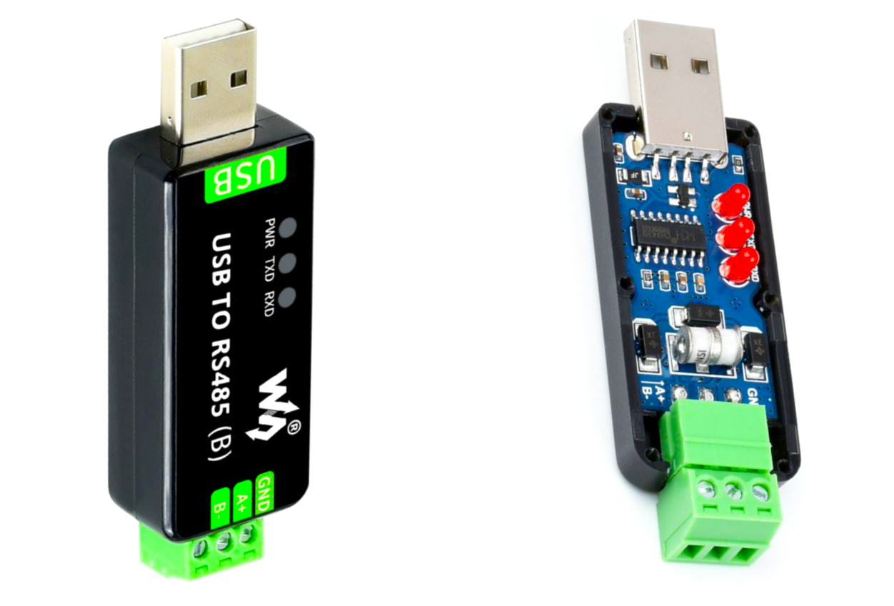
RS-485
The RS-485 is a standard developed in the year 1983 by both Electronic Industries Association (EIA) and the Telecommunications Industry Association (TIA).
RS-485 became the standard physical layer for automation protocols such as Modbus RTU and PROFIBUS. This is because it supports longer runs, higher speeds, and multiple devices.
The standard RS-485 specifies only the transmitter’s and receiver’s electrical characteristics (physical layer). It does not recommend or specify any communication protocol. It derives from RS-422 (differential pairs, end-of-line resistors) the maximum number of receivers is increased to 32.
The most interesting of its use is that RS-485 defines a 2-wire implementation as an alternative to the 4-wire RS-422. Thus, this aspect supplemented by the possibility of long distances has allowed the development of applications in the industry with process control.
Full Duplex and Half Duplex
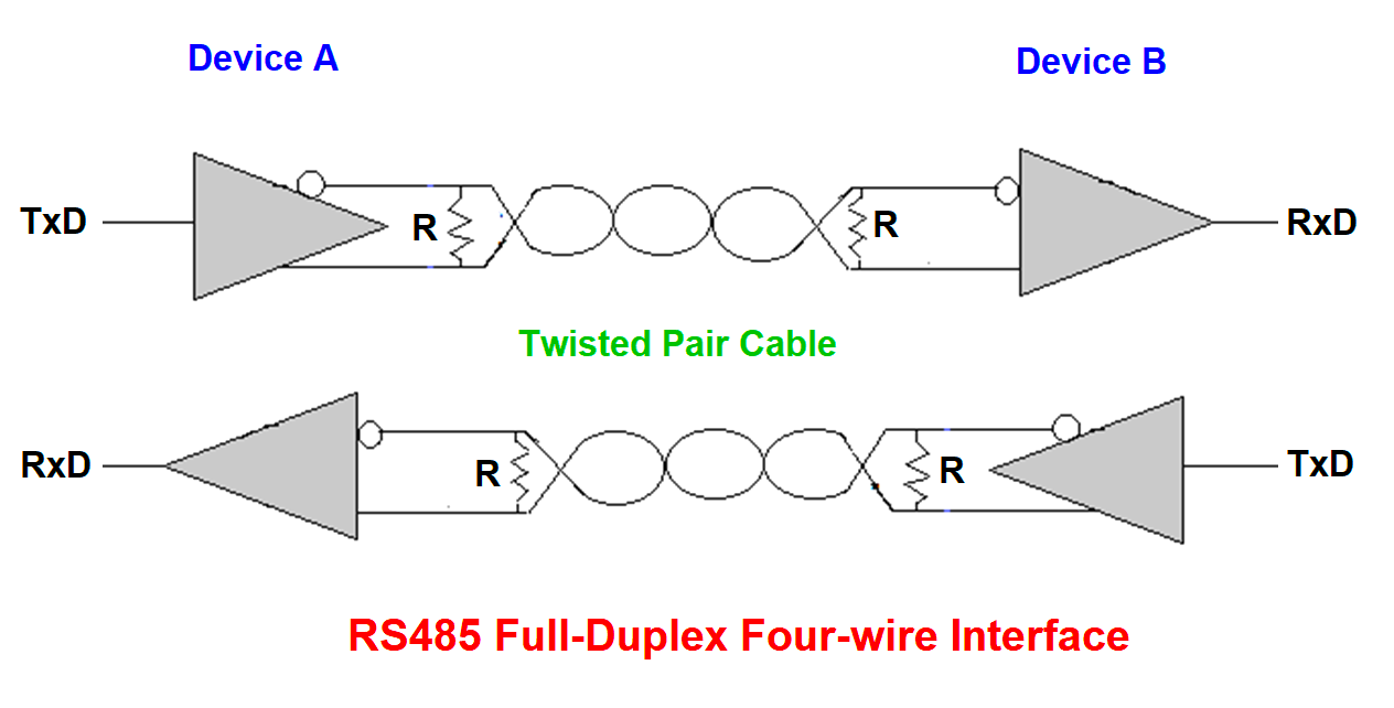
The RS-232 and RS-422 are called “Full-Duplex”, i.e. the system allows communication in both directions simultaneously (examples: telephony, or the two-way road).
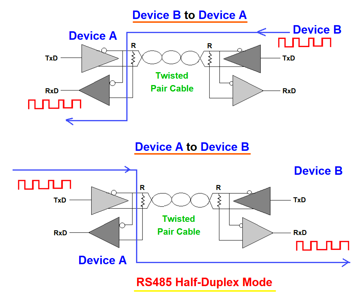
The Half-Duplex mode allows communication in both directions, but in only one direction at a time (for example the walkie-talkie or the single track of a railway). Two-wire RS-485 becomes half duplex.
As a result, the higher protocol layers are responsible for managing the line seizure.
Many Protocols
RS-485, only defines the physical layer, resulting in many implementation and protocol variations: Profibus, X25, X21, and HDLC (High-Level Data Link Control).
Serial communication and reliability may be impaired in a hazardous industrial environment. Cables for serial communication may be surrounded by electrical lines, motors, or equipment that produces static electricity. If so, serial devices can be damaged by the sudden; power surges produced by this type of equipment.
What is Surge Protection?
A surge is a high-amplitude, short-lived pulse that lasts only a few millionths of a second. The surge may be caused by power lines, large motors, or heavy equipment.
A surge protector can absorb this high amount of energy instantly and efficiently to prevent damage to connected devices.
Balanced Communication Lines
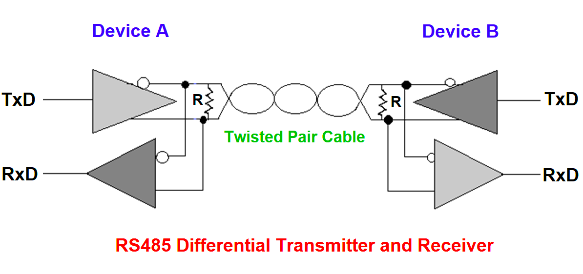
RS-485 and RS-422 are characterized by the use of a differential (or balanced) communication medium called the twisted pair. The transmitter and receiver circuits adopted in these interfaces use as the information on the difference between the voltage levels in each conductor of the twisted pair.
Binary codes are identified by the polarity (+ or -) of the voltage difference between the conductors of the pair, i.e. when the voltage in the “+” conductor is greater than that of the “- “conductor, a logic level is “1” is formed, when the voltage in the “- “conductor is higher than that of the “+” conductor, a logic level “0” is formed. A ± 0.2 V noise margin is set to increase interference tolerance.
This technique leads to the cancellation of noise induced in the transmission medium because if the same noise is induced in both conductors, the voltage difference between them does not change and the information is preserved. The electromagnetic interference emitted by a differential communication bus is also less than that emitted by non-differential communication because of differentials.
Termination Resistors
Communications theory describes the need for the termination of communications lines with value impedance corresponding to the transmission line’s characteristic impedance
A proper ending attenuates reflections that distort transmitted data, increasing the network’s speed and/or length limits. The terminator is shown in the above figures.
Uses
Rs-485 is still the most widely used protocol for POS (Point-of-sales), industrial, medical, consumer, and telecommunication applications.
Comparison between RS232, RS422, and RS485
| S. No | Characteristics | RS-232 | RS-422 | RS-485 |
|---|---|---|---|---|
| 1 | Differential | No | Yes | Yes |
| 2 | Max number of transmitters | 1 | 1 | 32 |
| 3 | Maximum number of receivers | 1 | 10 | 32 |
| 4 | Operating modes | Full-duplex, single-ended | Full-duplex, Half-duplex Differential | Full-duplex (4 wires), Half-duplex (2 wires), Differential |
| 5 | Network topology | Point-to-point | Multi-drop | Multi-drop |
| 6 | Max distance (low capacitance cable is used for long distances) | 50 ft (The widely used thumb rule) | 4000 ft | 4000 ft |
| 7 | Max speed | 20 kb/s | 10 Mbps down to 100 Kbps | 10 Mbps down to 100kbps |
| 8 | Receiver input sensitivity | ± 3V | ± 200mV | ± 200mV |
| 9 | Receiver input voltage range | ± 15V | 10V | -7V to +12V |
Image References – Practical Electronics: Components and Techniques by J.M.Hughes
Read Next:

Kumar
February 28, 2023Thanks for the basics.
gmcburgan
March 2, 2023Information on half-duplex, full-duplex, electrical levels,balanced communication, and comparison on three standards is very orderly explained.
ASchulz
September 5, 2024Muchas gracias por los conceptos de comunicación serial.
Muy bien presentado y fácil de entender.