Hello friends, I am working as a maintenance engineer in a company, and today I am going to share some practical insights from my job role, which will be useful for both electrical and instrumentation engineering graduates.
PLC Control Panel
Today I am going to share how a PLC control panel is made for particular industrial machines as per the application requirement.
Maintenance engineers also have to work as project engineers in the automation design company. Here the application is to make a panel for a machine that is currently working in manual mode that too with old mechanical actuators and relay logic electrical wiring. So our task is to upgrade this machine with PLC control panels to automate the process.
The way I am going to show is not as per any standards but this is as per thumb rules used by technicians in industries. Let’s begin the journey of making Panel
Step 1: Understand the Old Industrial Machine Application
Here, after meeting with the production person we came to know the application as follows:
This is an old machine that is designed with traditional relay logic. The operators face frequent issues with this old machine and it further affects their production. So they decided to upgrade their machine with PLC.
The operators do the following tasks on this old machine which are mentioned below. I shared the process/details in brief.
The ON button is pressed to start the machine, the hydraulic ON button is pressed to start the Hydraulic motor, and the coolant selector switch is pressed to start the coolant motor.
In auto mode, After pressing down Cycle button, the First top slide comes down and then the bottom slide goes down. Similarly, when pressing the UP cycle button, the bottom slide moves upwards, and then the top slide moves upwards.
In manual mode, by using the 4 individual buttons on the panel, we can move the top slide up and down & bottom slide up and down.
The PLC programmer must know the complete process of this old machine for developing the PLC program as per the existing application.

Step 2: Calculate PLC Inputs and Outputs
Now list the equipment used in the old machine panel and analyze the required inputs and outputs so that we can select the PLC modules as per the requirement.
Equipment used in the old machine:
- One hydraulic motor and 5 nos. 24-volt solenoid valves for the machine’s operation
- One motor for coolant
- 2 nos. limit switch for slide 1 up & down and 2 nos. limit switch for slide 2 up & down this is to know the different positions of the machine.
- Auto/manual selector switch, emergency switch, control ON push button, 2 push button for slide 1 manual mode up down, 2 push buttons for slide 2 manual mode up down, 2 push buttons for cycle start and cycle stop in auto mode and coolant ON/OFF selector switch.
- Control ON indication, tower light red, yellow & green indication.
- Some outputs may come in the future.
Therefore summing up we have 2 motors, 5 valves & 4 indications so a total of 11 digital outputs.
And limit switch, proximity sensor, all push buttons & switches we have 12 digital inputs.
Step 3: PLC Sizing and Selection of Modules
Based on stock, we have decided to use DELTA DVP14SS2 PLC which has inbuilt 8 digital inputs & 6 digital relay outputs. So we definitely need to use an extension module, so here we have used the DVP16SP module which has 8 digital inputs and 8 digital outputs considering future expansion this fits well.
We selected 5-ampere SMPS which is the low-cost SMPS as we have hardly 8 outputs that won’t consume much power.
If you have more inputs and outputs then you can calculate the size of SMPS by summing up all currents of load like the required current of all relay loads, solenoid coils, contactor coils, indicators, and other actuators based on applications like magnetic clamp/arm, stepper or dc motor, etc.
- The main hydraulic motor is 10 HP so its full load current will be 13 Amperes for that selected standard contactor size greater than this ampere and chosen MPCB with 120 to 140% of full load current (same thumb rule for coolant motor)
- We have 14 outputs So let us select 2 nos. 8 channel relay boards
- 32A 3 poles main MCB (not shown here because will have MCB in another distribution panel), 2 pole 6A MCB for control transformer, 2 pole 6A MCB for SMPS, 2A MCB for panel lighting and exhaust Fan, and 1 pole MCB for PLC.
- 6sqmm(carries 36A higher than total load ) connectors for main power, 4 sqmm (carries 24A higher than motor full load Amps ) connectors for the main hydraulic motor, and 2.5 sqmm connectors for all other motors, input, and outputs.
Step 4: Decide the Components Layout in the PLC Panel
The below shows the back plate of the panel where we have to mount all the components such as PLC, relays, contactors, terminal blocks, cable ducts, etc.
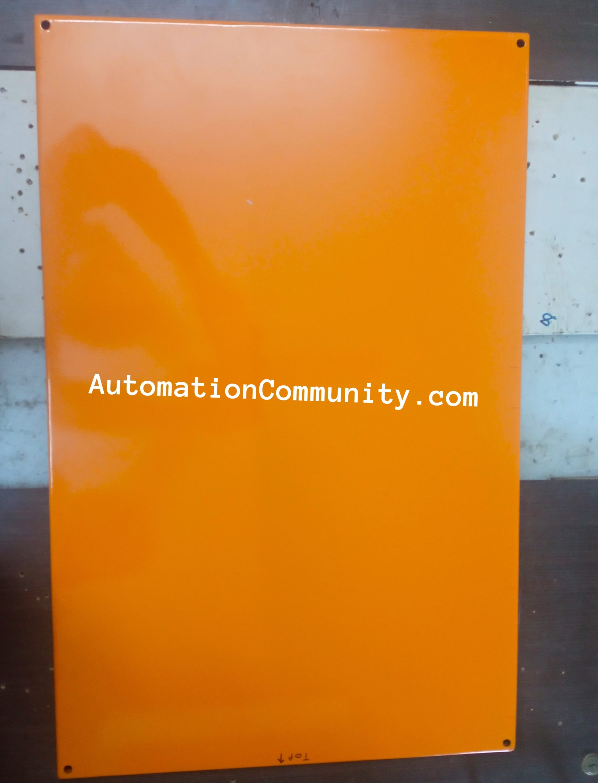
Based on your components, plan locations of equipment. Generally, at the top, we have PLC.
Next, we have the relay cards below the PLC modules.
Next, We have the MPCB & contactor, and at last connectors for terminating the field cables.
As per the components list, create a layout document.
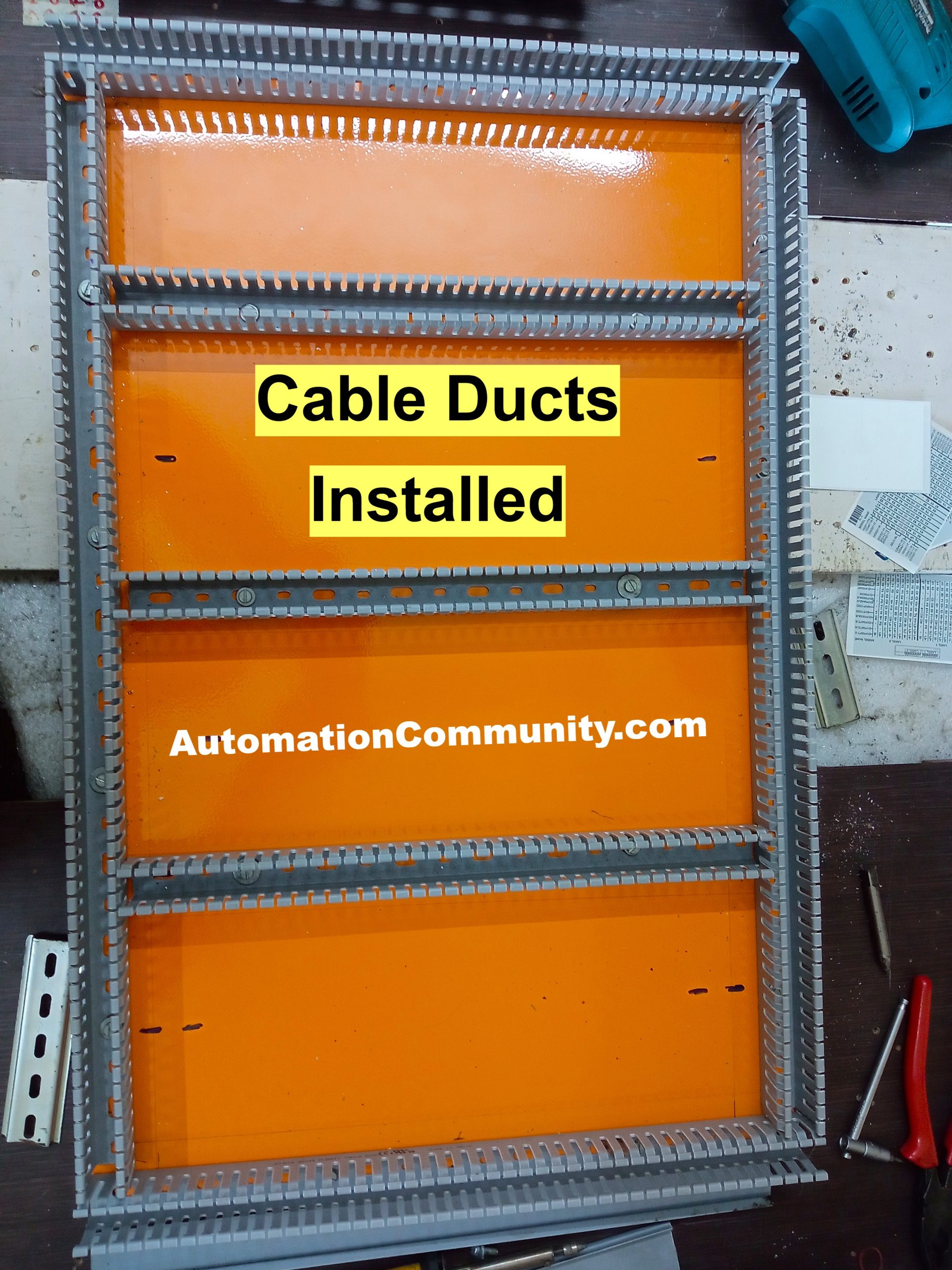
Step 5: Install Cable Ducts in the PLC Cabinet
After finalizing the PLC panel design, first, we have to install the cable ducts for housing the cables of PLC, relays, and other components.
First mark holes, then drill and thread holes. Then cut the PVC cable tray as per the requirement.
The below image shows the installation of cable ducts as per the plan.
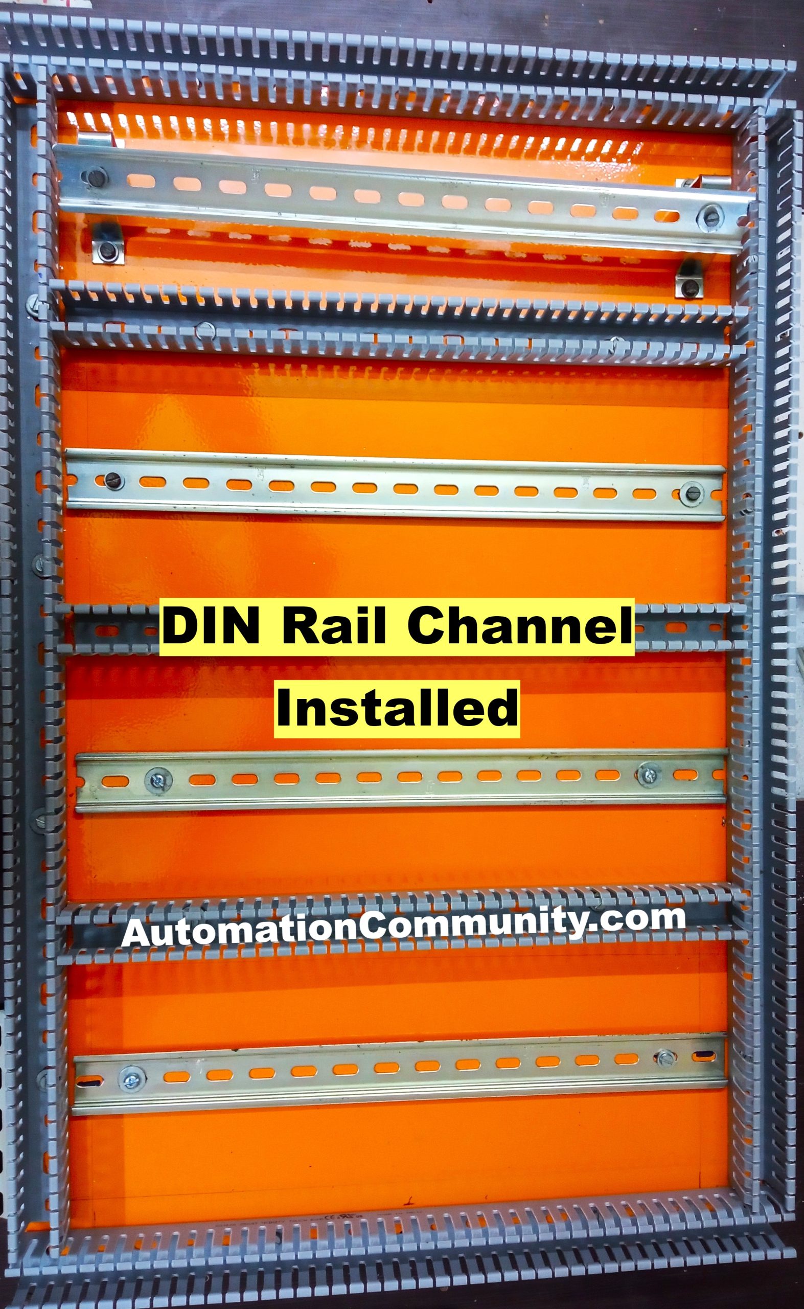
Step 6: Install DIN Rail Channels in the Panel
Next we have to install the DIN rail channel for mounting the components such as PLC modules, relays, etc.
The DIN rail provides support for holding these components in a panel. DIN rail is nothing but a perfectly shaped iron bar with a proper design for holding these components.
Here also, we have to mark and make holes and then install the DIN rails as per the design.
The below image shows the installation of DIN rail channels.
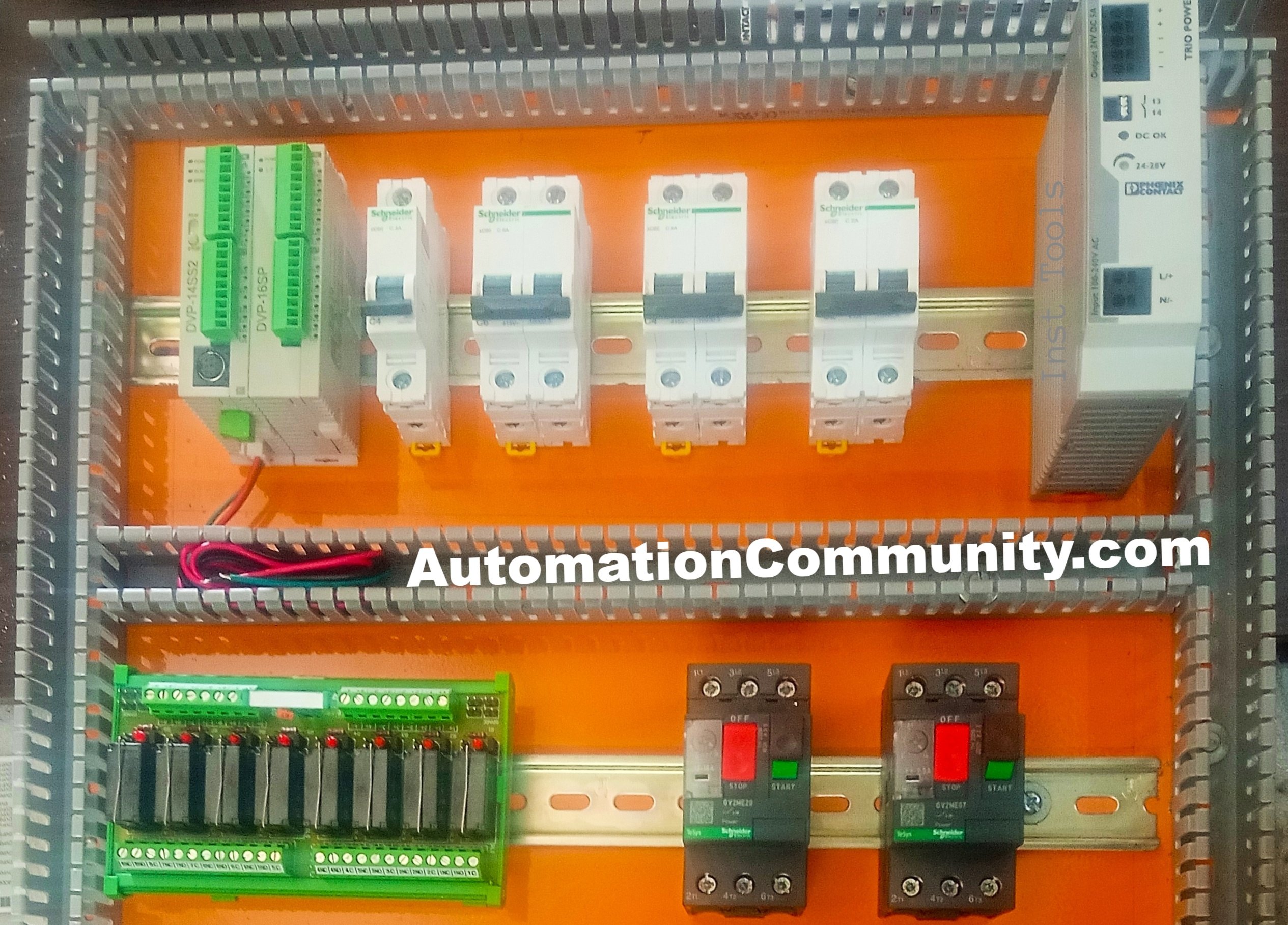
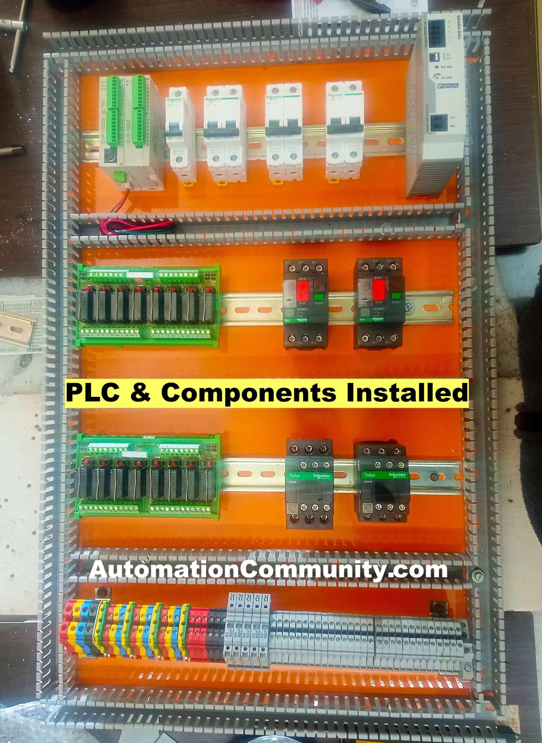
Step 7: Mount PLC and other Components
Now cable ducts and DIN rail channels are ready. Next, we have to mount the PLC and other components on the DIN rail channel.
You have to follow the layout document to understand the position of each component and install them as per the PLC panel design.
The below image shows the installation of all PLC panel components.
PLC and SCADA Courses:
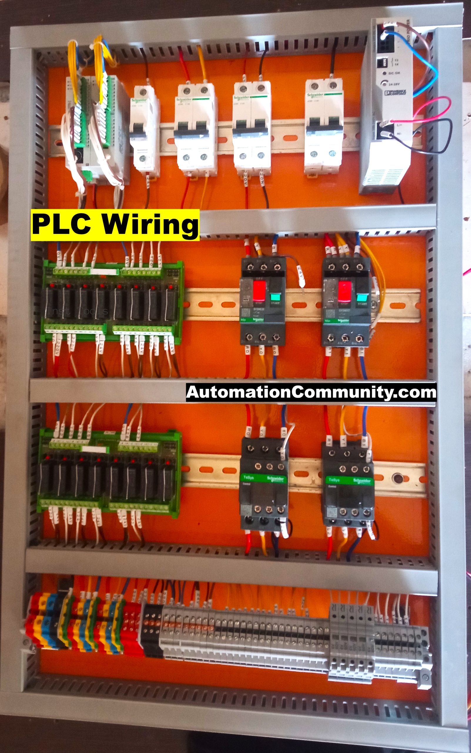
Step 8: PLC Wiring, Lugging & Ferules
In standard panels, lugs are fitted in wire for better clamping, and Ferules are added to the wire. So while doing troubleshooting one can easily trace the cables and also can understand control wiring.
There are different kinds of lugs available for different purposes like ring type, Pin type, Fork type, etc. But in the panel-making Pin type of lug is used and a ring-type lug can be used at the motor terminal box.
Besides that, we also have to decide the type of wiring for PLC that is sinking or sourcing wiring.
If we are using Sinking wiring for input then 0 volts will be given to the common of PLC and 24 Volt is going into the field and from the sensor/switches it comes to PLC, So for this type of wiring PNP sensors will be suitable. This is used in our case.
Another case is, if you don’t want to run 24-volt wiring In the field and want to do 0-volt switching then connect 24 volts to the common of PLC and 0 volts will be the common wire on the field side through the switch or NPN sensors 0 volts will be provided to inputs of PLC and input will be ON. (NPN sensors output wire provides ground to load and PNP sensors output wire gives 24 volts)
Similarly, on the output side, we can do either sinking or sourcing wiring.
Other wiring details are as follows:
- The main input wiring is 6 sqmm and the RYB is cable color code. These will go to 2 MPCB, Control MCB, and lighting MCB. Also, use a UPS power for the control components like PLC if available.
- The main hydraulic motor will have 4 sqmm wire (caries 24A higher than full load current )
- Coolant motor 1.5 sqmm wire ( caries up to 9A)
- For SMPS – 24V, GND, inputs and outputs 0.5 sqmm wire.(generally 0.5 sqmm for control wiring)
Step 9: Final Installation of PLC Control Panel
Now we finished the PLC panel installation at the vendor workshop. Then transport this panel to the machine location (customer site). Install the PLC panel as per the design.
Next, carry out the PLC inputs and outputs wiring. Here we have to disconnect all the field cables from the old machine panel and connect them to the new PLC panel as per the design.
Step 10: Testing of the PLC Program
The 3-phase main input power will be connected to the PLC panel. Disconnect all the outputs and then power up the panel.
Connect your laptop/engineering station with the PLC and download the PLC program.
Now carry out the testing of the program with the hardware and do the required changes in the PLC logic as per the requirement.
Here I shared the process in brief. There are lot many steps in the design of PLC panels for replacing the old relay-logic-based industrial machines.
Video – Building a PLC Panel
In the video, I explained how to design a PLC panel or an industrial control panel from the scratch.
Read Next:


Ram Kumar
February 1, 2023Very useful to me. Thanks bro
Mahadev
February 1, 2023Thanks. Please share details on detailed wiring of PLC with diagrams.
shankaramani viswanathan
February 5, 2023Excellent Very Practical and User Friendly