What is a Control Valve?
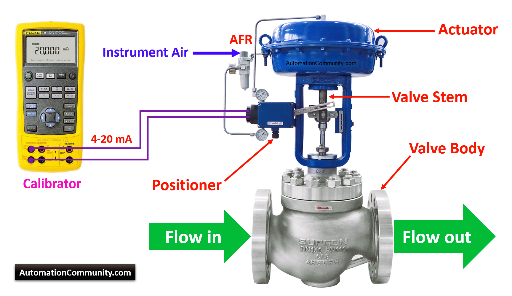
Control valves are devices that perform the function of regulating the flow of a fluid. The control valves receive the command signals from the PID controllers in a PLC or a DCS system. The valve positioners adjust the instrument air-flow to the valve actuator as per the received signal from the PLC or DCS systems.
This allows the control of the fluid flow through the valve and the consequent control of the variables of the process such as pressure, temperature, and level.
Valves are the main final control elements.
Basics of Control Valve
Control valves are classified into several types. According to the stem movement, they can be rotary or linear valves. Based on the action, they can be air to open or air to close. Based on its actuation, it can be a diaphragm or cylinder pressurized, and so on.
For a control valve that is serviced in an instrument workshop, the following steps are carried out as part of the calibration process.
List of Tools Required for Valve Calibration
- 4-20 mA calibrator or source feeder
- Regulator for supplying 3-15 PSI signal
- Regulator for 20 psi supply
- Pressure Gauge (3-15 PSI ranged)
- HART Communicator
- Datasheet (if applicable)
Calibration Procedure
Initially, a thoroughly serviced control valve needs to be calibrated in three stages.
- One is valve calibration without accessories. That is stroke checking.
- The next step is with the positioner (if the I/P converter is externally mounted).
- The last step is a positioner with an integral I/P converter (Smart Valve Positioner).
All above-said practices differ slightly from process plant to plant as per their particular needs.
Nowadays the calibration procedure of a control valve with a smart positioner is a popular method used in industries.
Before starting the job, take proper work permits and inform the process engineers and take the isolation of the valve if required. Place the PID controller in manual mode in the PLC or DCS systems.
Step-by-step procedure:
Control Valve Calibration Procedure Without Accessories
The below calibration procedure for a control valve without accessories.
1. To start calibrating a control valve, it is important to determine its operating range, that is, if it is 3-15 PSI, or split range (3-9 PSI, or 9-15 PSI), as well as to know the type of action, whether it is air to close or air to open the valve.
2. Once the operating range and the type of valve action have been determined, a pressure simulation will be applied to calibrate it. It is nothing but a stroke test to determine the full open and full closure of a valve.
3. Now, let us calibrate a valve with 3-15 PSI, if it is a reverse action (air to open) then the valve will be closed, it begins to simulate pressure little by little and it should start opening at approx. 3 PSI. The valve travel indicator must be at 0%.
4. When we apply with 3 PSI then the valve will be at 0%. Next, we proceed to apply 15 PSI then the valve must open 100%, and the stroke indication shows full scale.
5. If there is a problem with the 0% and 100% calibration then proceed to adjust the spring tension nut on the control valve until achieving the desired value.
6. The verification of 0% and 100% are repeated a number of times that are necessary until the valve is correctly calibrated.
Note: the above steps have been done with a reverse-acting valve (closes no air).
The calibration of a direct-acting valve (without air opening) would be done in reverse, that is, at 15 PSI the valve should be closed while at 3 PSI it would be completely open. The open and close percentages also change inversely.
Control Valve with Pneumatic Positioner Calibration
The below calibration procedure for a control valve with a pneumatic positioner.
1. Once the control valve is calibrated without accessories installed, proceed to do it with one of them (Positioner).
2. To calibrate the automatic valve with a pneumatic Positioner, an air regulator is installed to the valve body or attached to the Positioner directly and an air supply of 20 PSI. Apply 3-15 PSI from a fine regulator and sends an opening signal to the valve.
3. With a signal of 3 PSI the valve must be at 0%. If it is not the case with the Zero screw you adjust the position of the valve so that it is closed.
4. When the positioner sends 15 PSI output to the valve actuator the valve adjusts its position to 100%. If not the case, adjust the span screw so that it gives said opening value.
5. As many times as necessary, these steps will be repeated until the valve shows correct readings i.e. open and close parameters.
6. Once the percentages of 0% and 100% have been adjusted, the intermediate values will be checked.
Control Valve with Smart Positioner Calibration Procedure
The below calibration procedure for a control valve with a smart positioner. We can also call this an electro-pneumatic positioner with a control valve.
1. In the calibration procedure of a pneumatic Positioner this is done mechanically and with control air.
2. In the case of an electro-pneumatic positioner, it works with a 4 – 20 mA current signal and controls air through the valve actuator.
3. To check the 0% opening of the valve, 4 mA is simulated to the electronic positioner, and this will show the valve’s 0% position. If this percentage of the opening is not achieved, then connect the HART communicator to the valve positioner and start calibration.
4. To check the 100% opening, 20 mA is simulated and this will show the valve’s 100% position. If there is some problem then connect the HART communicator to the valve positioner and then start the calibration.
5. In some control valves, you will be provided with a display and control buttons. You can use these to check the valve position status and also you can start the calibration. (no need for a HART communicator)
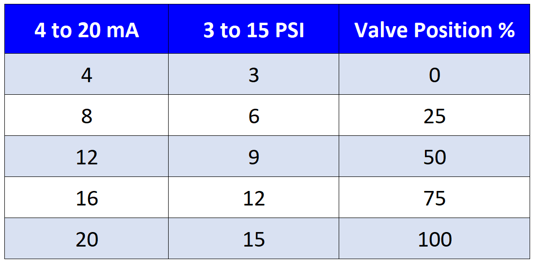
6. Once the percentages of 0% and 100% have been calibrated, the intermediate values also will be verified, like 8 mA -> 25%, 12 mA -> 50%, and 16 mA -> 75%.
Table of Control Valve Opening Percentages
Keywords
Air to open: The air-to-open control valve is held close by the spring force, and the pneumatic signal makes it open. Also called Reverse action.
Air to close: The air-to-close control valve requires a pneumatic signal to move towards a close position. Also called Direct action.
AFR: AFR means Air Filter Regulator. The AFR is used to adjust the required instrument air to the control valve.

Mansour DIOP instrumentiste
October 29, 2022Pertinent… Merci
ahmed messallam
January 17, 2024great information, thank you.
Emin Can
October 10, 2024Perfect information. Thanks
Muhammad Younis Bugti
October 18, 2024Dear sir, Please. Email Reply back . Name Poynton Valves LTD, What is Repairing System Basics of Control Valve. and attached picture. Sent please
Hoan Pham
January 3, 2025thank you!
Radoslav Radoslavov
April 27, 2025Thanks for helping!