Description
The Capacitance Type Level Switch is designed with two versions: Integral and Two Part.
The Integral version has the controller integrated with the probe, while the Two Part version has the controller mounted separately from the probe, allowing for remote installation.
Capacitance Type Level Switch

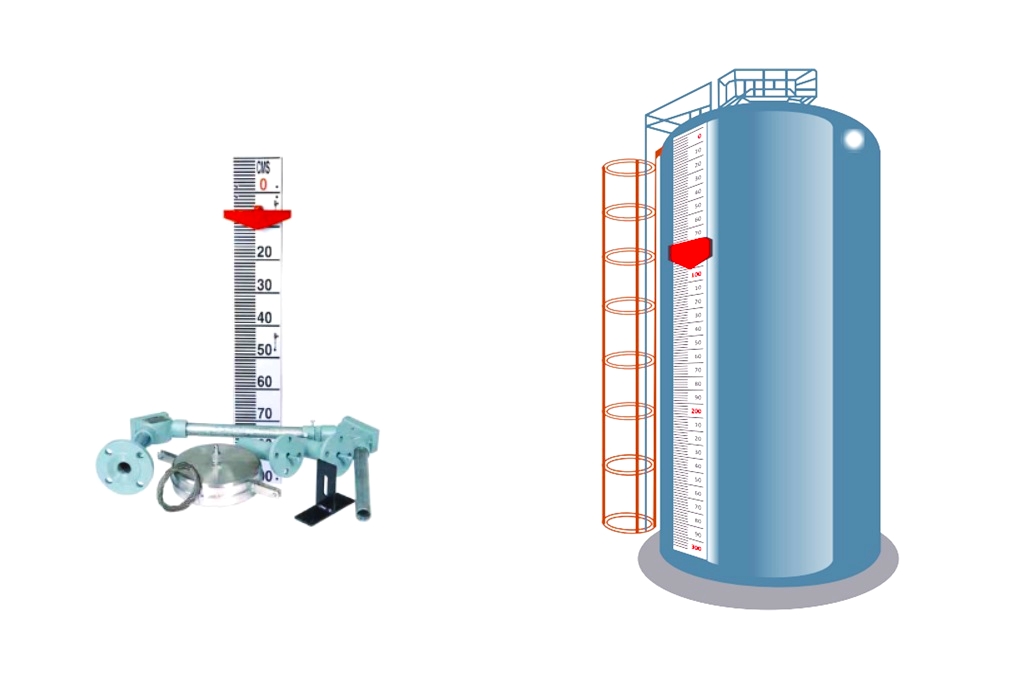
The probe can be mounted either on the top or side (inclined) of the tank. The principle of measurement is based on the capacitance formed between the sensing electrode and the metallic tank wall (ground electrode), which changes according to the liquid level.
The capacitance is detected and converted into a voltage signal that triggers the relay for switch actuation.
Features
The Capacitance Type Level Switch has the following features:
- Cost-effective and reliable with no moving parts.
- Easy to install and set field-adjustable switch points.
- A settable fail-safe mode ensures safety during operation.
- A variety of electrode constructions are available to suit a wide range of services.
Specifications of Capacitance Level Switch

Sensing Probe
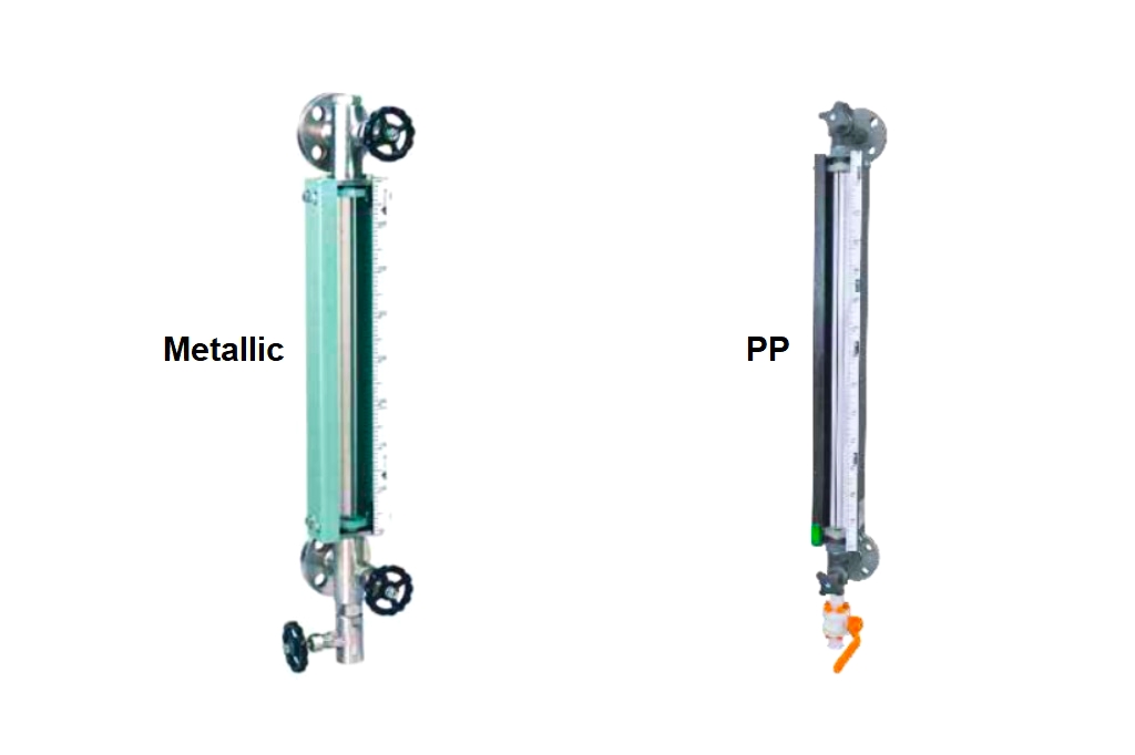
- Enclosure: Cast Al IP66 or ABS x IP65
- Cable Gland: PG11, Polyamide
- Probe Type: Rigid Electrode- Range: 200-1500mm, Flexible Electrode – Range: 1500-5000mm, Concentric Pipe Electrode – Range: 200-1500mm. for low dielectric liquids)
- Installation: Top / Side
- Sensing Electrode: SS304 or SS316 PTFE insulated.
- Ground Electrode: Bare or PTFE insulated for corrosive applications.
- Process Connection: 40 NB flange / 50 mm tri-clover ferrule for metal tanks.
- Max Temperature: 60°C
- Max Pressure: 5Kg/cm²
Controller
- Enclosure: Cast Al IP 65
- Enclosure Dimensions: Sq. 147mm x 75mm Ht
- Conduit Connection: Polyamide PG 11
- Power Supply: 90-270 VAC, 50-60 Hz, or 24 VDC
- Control Set Points: Max. Four
- Output: SPDT 5A, 250 VAC / DPDT(Optional)
- Operating Diff.: 15 to 20mm
- Indication: LED indication for power & relay status
- Safety Operation: Field selectable failsafe high & low
- Capacitance Range: 100 to 5000 pf
- Dielectric constant: > 1.8
- Accuracy: ±1%
- Repeatability: ±0.5%
Installation of Capacitance Level Switch

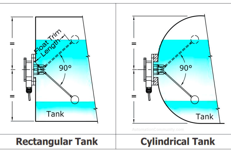
The probe for the Capacitance Type Level Switch can be top or side (inclined) mounted.
Here are some guidelines for installation:
- Choose a suitable location for the probe on the tank where there is minimal turbulence.
- Position the probe to avoid the direct flow of material onto it.
- Ensure that the process connection of the level switch matches that of the tank.
- Ensure that the sensing electrode is parallel to the reference probe/tank wall.
- For outdoor installations, protect the electronics from direct sunlight.
- In the two-part system, mount the controller on the wall using the two mounting holes provided on the enclosure.
- Make sure that the mounting surface for the controller is flat and not subject to vibrations.
- Avoid mounting the controller in close proximity to high-voltage cables, and contractor/drive control.
- Do not mount the controller in a confined space where the temperature may exceed the rated temperature.
- The controller is provided with an 8-pin DIP switch. Refer to the table below for various switch combinations for FSH, FSL, and latching operations between the level set points.
Precautions
Here are some precautions to take when using the Capacitance Type Level Switch:
- Make sure the switch is properly grounded.
- Keep the supply wiring away from power cables, contactors, and motors.
- Ensure that the enclosure of the probe and controller is closed tightly with the cover and gasket. There should be no gaps between the cable’s outer diameter and the cable gland’s inner diameter.
- Double-check that all wiring is complete and correct before turning on the power supply.
- When using an inductive load, it is recommended to use a suitable snubber across the contactor/relay coil and a MOV (Metal Oxide Varistor) across the NO (Normally Open) contact of the relay.
Field Setting of Switch Point
To set the switch points for the Capacitance Type Level Switch in the field, each point should be adjusted individually at the installation site, taking into account the actual dielectric constant of the process medium under operating conditions.
Follow these steps:
- Connect the capacitance switch according to the wiring diagram.
- Fill the tank with the actual process medium under operating conditions up to the desired level where the respective switch point is to be set. Turn the potentiometer of the switch in question clockwise or counterclockwise until its corresponding LED lights up.
- Repeat step 2 for all switch points.
- Empty the tank and refill it to verify the accuracy of all switch points under site conditions. The instrument is now configured for the desired switch points and is ready for use.
Periodic Maintenance
To ensure the proper functioning of the Capacitance Type Level Switch, it is important to perform periodic maintenance.
This includes checking and tightening any loose electric connections and terminals, as well as tightening the nuts and bolts of the process connection. It is also important to visually inspect the electrode insulation for any signs of damage and clean the electrode periodically.
Once maintenance is complete, the enclosure should be closed with its cover and gasket to maintain weather proofed.
Troubleshooting Capacitance Type Level Switch
Some of the problems and solutions of Capacitance Type Level Switches are mentioned below.


Featured