Bi-color Multi Port Level Gauge (TBLG) – Pune Techtrol
Description
The Bi-color Multi Port Level Gauge is designed for use in high-pressure steam boilers and containers to provide a continuous indication of water levels.
This level gauge is composed of several components, including a liquid chamber, port assemblies, an illuminator, and isolation valves.
Bi-color Multi Port Level Gauge
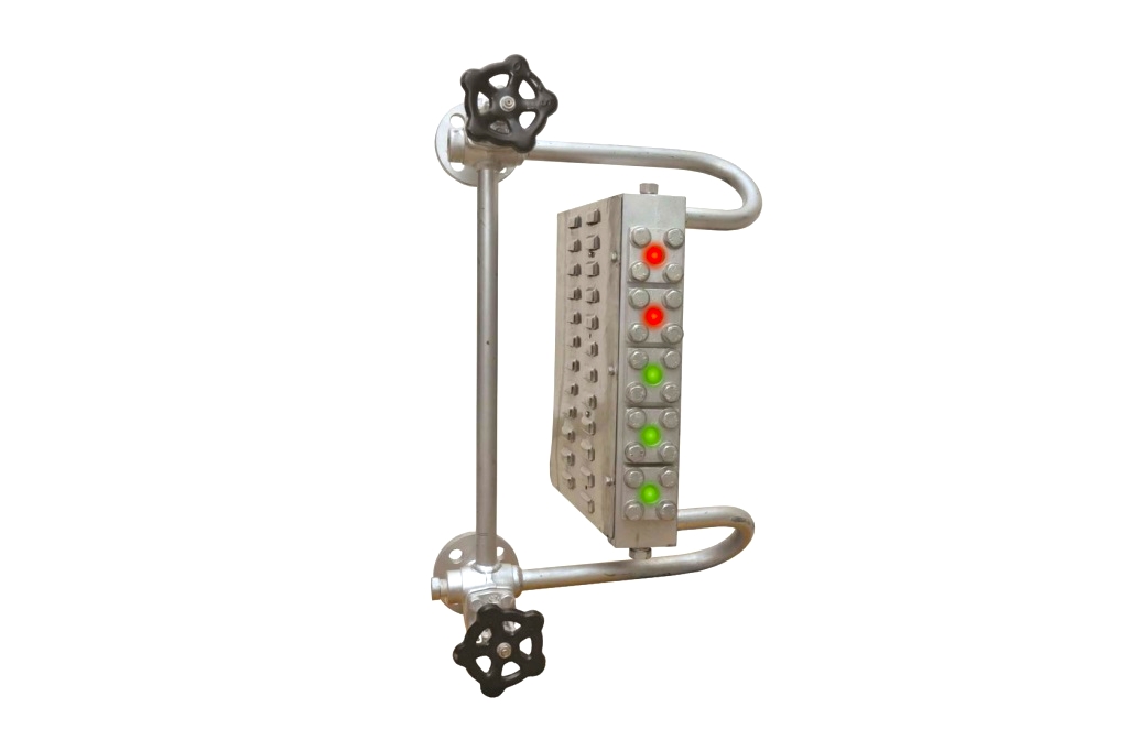
The Bi-color Multi Port Level Gauge features a liquid chamber with a trapezoid shape, which is designed with equispaced ports along its nonparallel sides.
In this level gauge, each port is equipped with circular gauge glass, a mica sheet, a gasket, a cushion, and a port cover, which is fitted with bolts from both sides of the chamber.
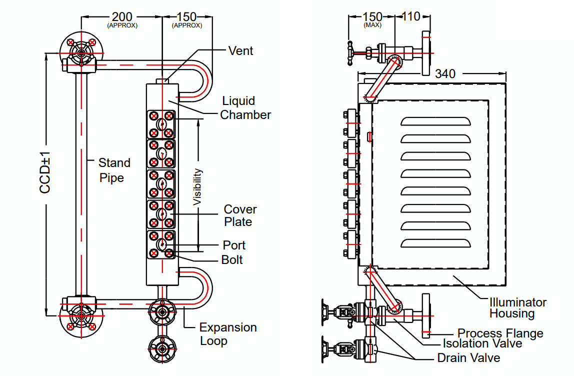
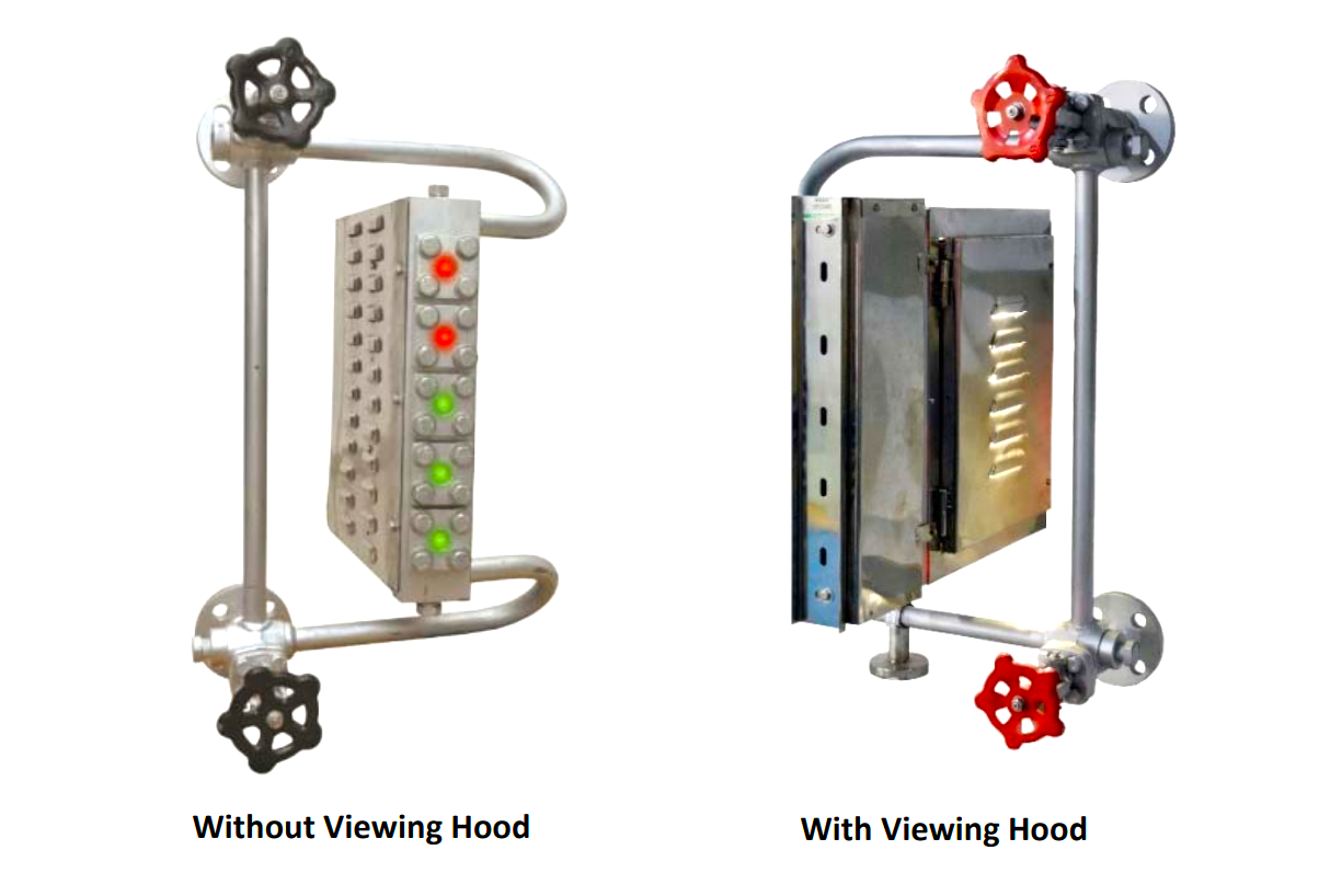
The level gauge also includes an illuminator, which is made up of a steel enclosure with ventilating louvers at the back, housing a bicolor glass filter that features red and green colors, as well as a light source. This illuminator serves to enhance the visibility of the gauge.
The liquid chamber of the Bi-color Multi Port Level Gauge is fitted between two end blocks, which are connected through single or double expansion loops. A standpipe is also included with a double expansion loop to improve circulation and ensure durability.
Two drain valves are provided for added safety so that if one valve becomes inoperable, the other can still be used.
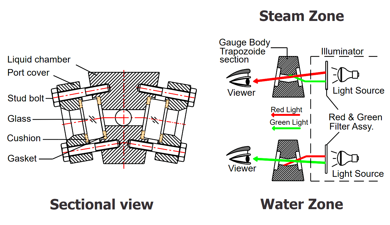
The bi-color multi-port level gauge operates on the principle of refracted light passing through a trapezoid-shaped chamber. This chamber is equipped with a series of equidistant ports that are fitted with circular gauge glasses, mica sheets, gaskets, cushions, and port covers.
The light source from the illuminator passes through a bi-colored filter assembly and falls onto the inclined glass, which refracts the light according to the refractive index of the water or steam. This refraction causes the light to appear red when passing through steam and green when passing through water, enabling the viewer to determine the level of liquid present in the container.
The Bi-color Multi Port Level Gauge applications in various areas, including boiler drums, feed water, and process heaters in utility, recovery, or fluidized bed boilers.
Technical Specifications
- Process Connection: 3/4″ or 1″ Socket weld / ANSI Flange
- Process Connection MOC: a) CS A 105 (IBR), b) ASTM A 182 F
- Isolation Valve: a) CS A 105, SS304 / SS316 x Integral Offset Needle Valve x ABC x Bolted bonnet (IBR) b) CS A 105, ASTM A 182 F SS304 / SS316 x Integral Offset Needle Valve x ABC x Bolted bonnet (Non-IBR)
- Stand Pipe MOC: CS A 106 Gr B or ASTM A 312 TP SS304 / SS316
- Expansion Loop MOC: CS A 106 Gr B or ASTM A 312 TP SS304 / SS316
- Vent: 1/2″ NPT Plug
- Drain Valves (2 Nos): 1/2″ Socket Globe Valve x CS SA 516 Gr. 70 or ASTM A182 F SS304
- CC Distance: 600 to 1500mm
- No of Ports: 5 to 21
- CC Dist between Ports: 70mm
- Visible Port dia: 15mm
- Gauge Mtg. Orientation: Left or Right
- Illuminator: LED bulb x 230VAC, 50 Hz
- Max Temperature: 300°C
- Max Pressure: 70 Kg/cm2
Commissioning of Level Gauge
Here are the steps for commissioning and placing a level gauge in service:
- Any shut-off valves between the gauge and boiler and open the gauge drain, completely emptying the gauge of its contents.
- If shut-off valves are not provided, relieve the pressure in the vessel/boiler.
- Fully open the gauge drain valves.
- Open the upper and lower drum isolation valves.
- Slowly open the upper gauge isolation valve.
- Allow the gauge to heat up without pressure buildup for 10 minutes.
- Gradually close the drain valve over a 15-minute interval to allow pressure to increase slowly in the gauge.
- Close the gauge drain valve fully.
- Fully open the upper gauge isolation valve.
- Open the lower gauge isolation valve.
Steps to remove the gauge from service:
- If upper and lower drum isolation valves are provided, close them.
- Close the upper and lower gauge isolation valves.
- Open the drain valve slowly to depressurize the gauge gradually. This process should take at least 15 minutes.
- Once depressurized, fully open the drain valve.
Port Inspection Procedure:
- Take the gauge out of the vessel and place it on a workbench.
- Examine the mica glass in each port visually by using a flashlight and check for a white or opaque appearance.
- While illuminating the port with a flashlight from the backside, check both sides of the gauge.
- Any port with a white or opaque appearance must be replaced before putting the gauge back into service. Operating with such ports can lead to glass failure and dangerous discharge of high-temperature steam.
- To replace the glass or mica sheet, refer to procedure 8.
Gauge and Water Column Blowdown Procedure:
To ensure proper level indication and visibility of the gauge, sediment build-up in the connecting pipes, valves, and mica must be eliminated. Excessive blowdown, however, should be avoided as it can reduce mica life.
Follow the steps below while the gauge is in service:
- Close the upper gauge valve.
- Slowly open the gauge drain valve for about a minute to clear sediment from the lower gauge piping and valve. Then, shut the gauge drain valve.
- Open the upper gauge valve.
- Shut the lower gauge isolation valve.
- Slowly open the gauge drain valve to clear sediment from the gauge, upper gauge piping, and valve. Shut the gauge drain valve.
- Open the lower gauge isolation valve.
- Check the gauge for clarity. If necessary, repeat the procedure.
Maintenance Checklist
- Follow the inspection and maintenance schedule to ensure the mica-glass-gasket assembly is replaced before the mica protective shield is dissolved.
- Promptly replace gauge glass that appears white or is opaque to avoid sudden discharge of hazardous high-temperature steam.
- Keep the level gauge, connecting pipes, and valves free from obstructions caused by sediment to ensure proper level indication.
- Blown down the gauge as required to eliminate sediment according to the preventative maintenance blowdown schedule.
- Check for any leakages near the gasket, change it if necessary, and re-tighten the bolts.
- Check for loose electrical connections and retighten them.
- When removing the instrument from any vessel, ensure it is a 2 man operation and the assembly is kept vertical to prevent damage to the lever assembly.
- Check periodically for faulty LED bulbs and replace them if necessary.
Troubleshooting Bi-color Level Gauges
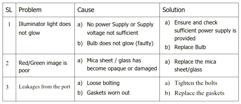
Some of the common problems and solutions of bi-color level gauges are mentioned in the below table.
Location
Report abuse
Report abuse
Featured


