Pressure Transmitter Calibration Procedure
What is a Pressure Transmitter?
A pressure transmitter is a device that converts an applied pressure into an electrical signal. This electrical signal can be a voltage or current (an analog signal proportional to pressure), digital, or even a composite. That is, it can be both analog and digital, where the digital is a modulation added to the analog.
This conversion is generated using means of the sensitive element or transducer such as resistive, capacitive, piezo-resistive, piezoelectric, etc.
Basics of Pressure Measurement
Pressure is a scalar physical quantity and is defined as an amount of force exerted on a unit surface, represented by the symbol P. It is measured in the International System (SI) in pascals.
Other units of pressure measurement include bar, atmosphere, and millimeters of mercury column. Pressure can be categorized according to the following types
Absolute Pressure
In simple terms, it is the pressure exerted by some element as well as the pressure of the atmosphere on a body.
Atmospheric Pressure
It is the pressure exerted by the whole mass of gases in the atmosphere on the earth’s surface and on everything that rests on it. As one rises above the sea level, atmospheric pressure decreases since there is less air mass above us.
Gauge Pressure
It is the most widely used in everyday life. The pressure that exists above the value of atmospheric pressure. The difference between absolute pressure and atmospheric pressure is known as Gauge or relative pressure.
Tools Required for Calibration
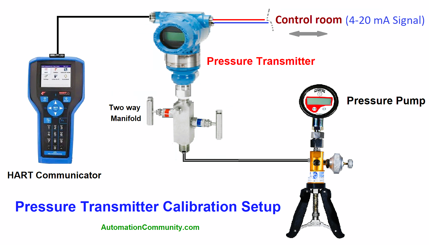
- HART Communicator
- Handheld Pressure pump
- All tools and equipment (adjustment wrenches, screwdrivers, etc.)
Pressure Transmitter Calibration Procedure

For the calibration, the following steps must be taken into account.
Take work permit, Safety rules to be followed (wear PPE), and complete the toolbox meeting before starting the calibration process. The area of calibration should be free from vibrations.
Close the 2-way manifold of the fluid inlet to the transmitter.
Open purge to depressurize the pressure in the intake tubing.
Open the rear cover of the transmitter
Connect the cable from the HART communicator to the transmitter, and verify the polarity of the transmitter. Check the transmitter to be able to communicate with the instrument.
Using the field communicator’s HART protocol – make sure to connect the polarity of the communicator with the instrument.
When turning on the communicators, select the HART option in the main menu for communication with the instrument. To avoid communication conflicts, pay attention to connecting the cable in the HART slot only).
Allow the online connection with the field communicator, waiting for it to load for a few seconds.
The instrument calibration range (LRV and URV) will appear on the screen, verifying the real primary values found, as well as verifying its analog output (AO) of 4 mA and 20 mA.
Next, proceed to connect the handheld pressure pump.
Proceed to increase the pressure to 0, 25, 50, and 100% of the calibration range of the transmitter.
If different values are found in its lower and upper ranges, proceed to calibrate the transmitter.
On the main menu screen, go to Device setup, then to process variables, and finally to calibration.
Once you click on calibration, go to the option Trim sensor to perform zero pressure adjustment 4mA. Enter Zero trim.
Verifying the result, it must have improved the value by 0.000 PSI. Then proceed to perform your lower trim, follow the same procedure as the Zero Trim with the difference of entering the Lower Sensor Trim option.
This point is only made when there is a lot of difference in value. Check its analog output signal for an approximate value of 4 mA.
To perform the Upper calibration, apply pressure with the pneumatic pump up to the maximum calibration range.
On the main menu screen, enter Device Setup, then to the Process Variables option, and finally Calibration.
Next, check for the Process connection value high and enter Upper Sensor Trim.
Follow the steps by pressing Next until the calibration is finished.
Verify the result of the pressure and its analog signal (20mA).
Carry out a new verification by increasing values from 0 to 100%, zero, and span and check and record these values with the initial values, before calibration.
Verify the error percentage of a transmitter according to the model.
After calibration, check values with the control room.
Install the pressure transmitter manifold and connect its tubing connection for tightness with no leaks. Proceed to hand over the transmitter in service, close its purge valve, and then proceed to open the main inlet valve to the transmitter.
Keywords
Hydrostatic pressure
Hydrostatic pressure is the pressure experienced by both due to the weight of the fluid itself at rest.
Hydrodynamic Pressure
It is the pressure experienced by fluids and in constant motion.


