By using this site, you agree to the Privacy Policy and Terms of Use.
Accept
Automation CommunityAutomation Community
  • PLC
  • Control Systems
  • Instrumentation
  • Calibration
  • Electrical
  • Courses
    • Siemens PLC Course
    • Allen Bradley PLC Course
    • InTouch SCADA Course
    • WinCC SCADA Course
    • Siemens Tia Portal
    • Omron PLC Course
    • Advanced PLC Course
Search
  • Customize Interests
  • My Bookmarks
© Automation Community. All Rights Reserved.
Reading: Modbus Communication between Mitsubishi HMI and Delta VFD
Share
Notification Show More
Aa
Automation CommunityAutomation Community
Aa
  • PLC
  • Control Systems
  • Instrumentation
Search
  • PLC
  • Control Systems
  • Instrumentation
  • Calibration
  • Electrical
  • Courses
    • Siemens PLC Course
    • Allen Bradley PLC Course
    • InTouch SCADA Course
    • WinCC SCADA Course
    • Siemens Tia Portal
    • Omron PLC Course
    • Advanced PLC Course
Follow US
© 2023. All Rights Reserved.
Automation Community > Blog > PLC > Modbus Communication between Mitsubishi HMI and Delta VFD
PLC

Modbus Communication between Mitsubishi HMI and Delta VFD

Editorial Staff
Last updated: 2023/04/29 at 4:06 PM
Editorial Staff
Share
5 Min Read
SHARE

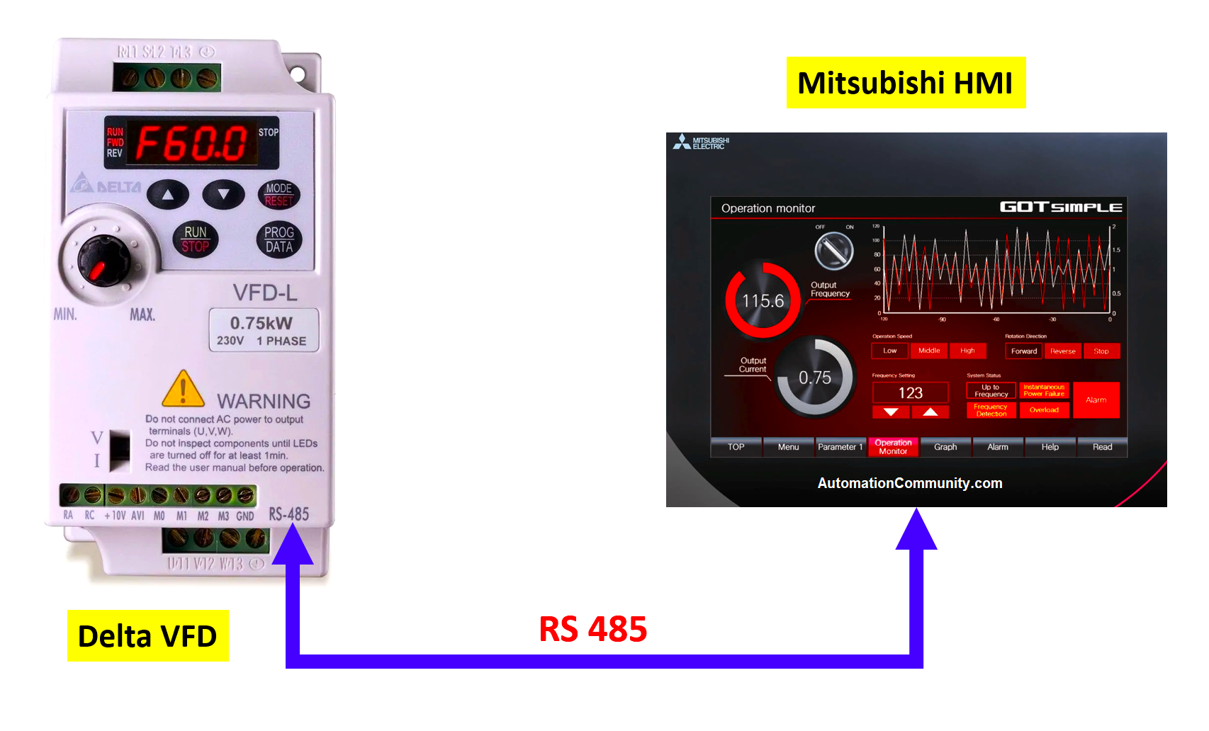
Modbus communication between Mitsubishi HMI (GS series) and Delta VFD (VFD-L)

In this topic, an Induction motor is controlled by delta VFD through Mitsubishi HMI.

There is no PLC used in this application.

The speed of the motor is controlled by feeding the values in the Numeric inputs placed on the HMI screen as directed by the Instruction manual of the VFD just to show the communication of HMI and VFD.

Mitsubishi HMI and Delta VFD

Here, the Induction motor is not controlled by the external terminals (Digital or Analog Inputs) of the VFD, rather we will use the RS485 port for running, stopping, and speed varying.

Different VFDs require different sorts of values for the specific Modbus Addresses to start, stop and vary the speed when the RS485 protocol is used. We are here to use those values only, to execute the said process.

For the implementation,

a) VFD and HMI should be correctly connected through the communication cable

b) VFD needs to be properly parameterized with the communication settings such as Baud rate, Parity bits, Device Address, etc.

c) HMI configuration should be done according to the communication parameters set in VFD

Modbus Communication between Mitsubishi HMI and Delta VFD

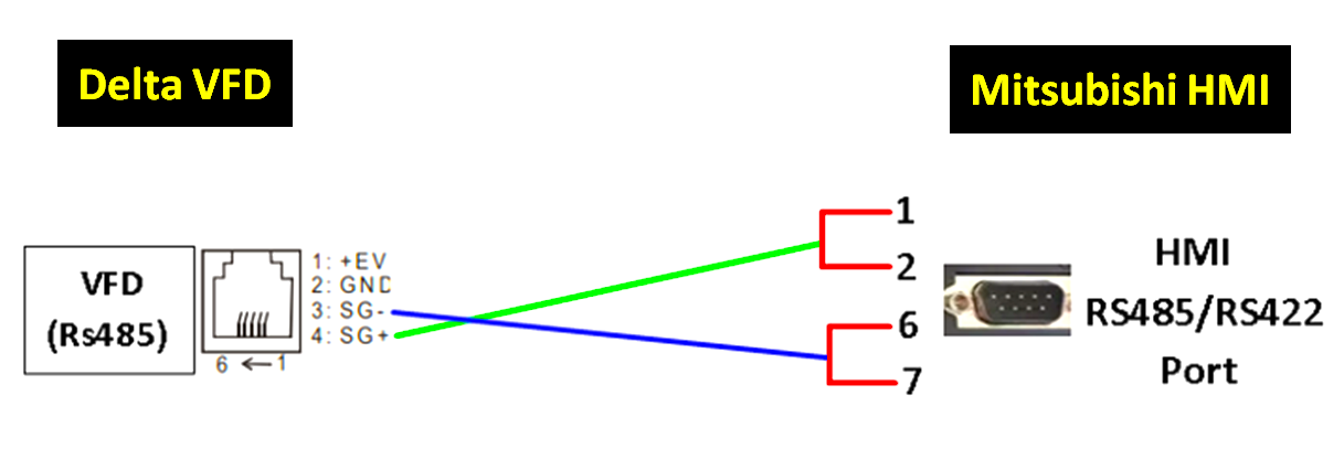
Cable Connection details of HMI and VFD on RS485 protocol are shown below.

Cable Connection of HMI and VFD on RS485

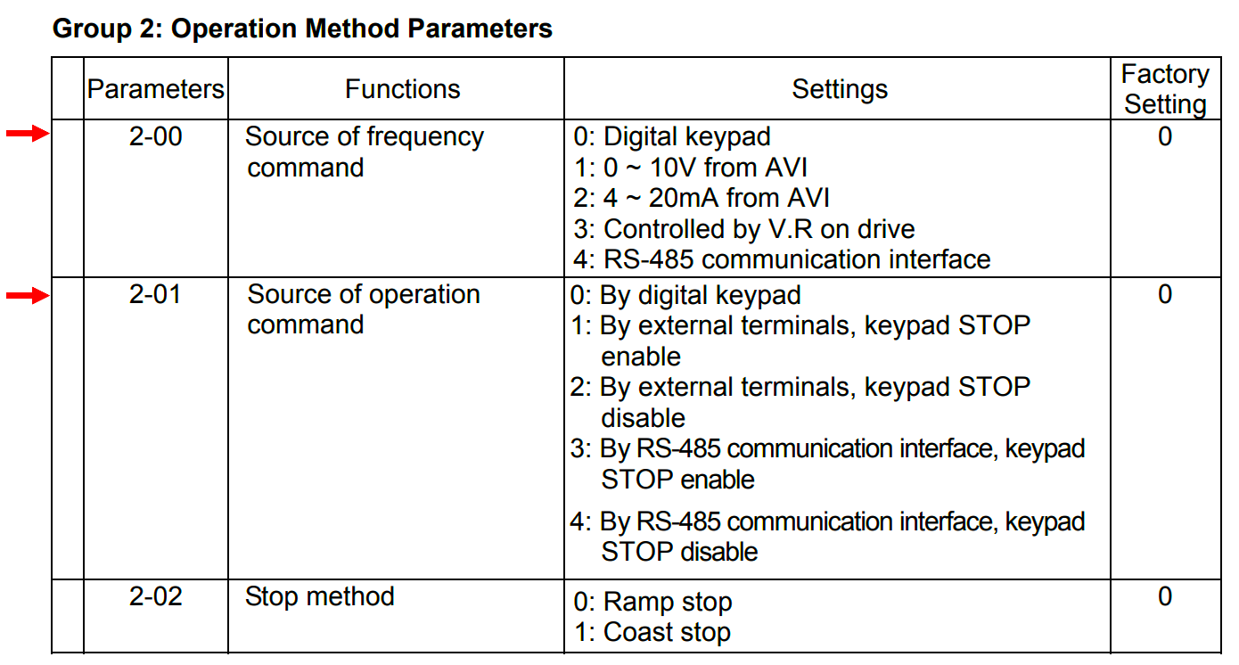
The mode of Communication is defined in the Group 2 parameter section of the VFD.

Set both 2-00 and 2-01 as “4”

Operation Method Parameters of Delta VFD

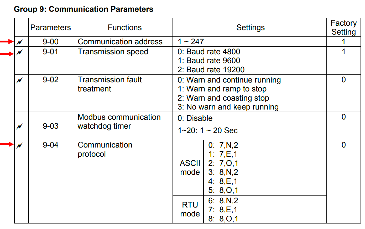
Communication settings are done in the Group 9 parameter section of the VFD.

The station address (Slave ID) of any device is used to identify each device in a system. All the other parameters need to be matched at each station.

More Read

30 Communication Protocols in Automation and Instrumentation

RS232 RS485 RS422 Communication Protocols – Questions and Answers

Serial Communication Questions and Answers

Profibus Questions and Answers

Stepper Motor Questions and Answers

Define the Slave ID as “2” in the parameter 9-00 and set 9-01 (Baud rate) to “2”

Set 9-04 to “6” (RTU mode, parity None and Stop bits equal to 2)

Communication Parametes of Delta VFD

After selecting “New” in the “Project” Section, choose the series as “GS”. In GOT Type setting, choose the model as “GS2107-WTBD-N”. Then Click “Next”.

After confirming the above settings on the next page, select “Modbus” as Manufacturer and define HMI as “Modbus Master” in Controller type. Then Click “Next”.

Click Next after selecting the Interface as RS422/RS485

In Communication Driver’s “Detail setting” window, settings should be made according to the set parameters in VFD.

Define the Host address (Station address) differently from the VFD one. Here, 1 is defined which is different from 2. Ensure that Function codes 0F and 10F are selected as “Unused”.

After confirming the above settings, leave the screen switching settings as the default one and press “Next”.

Select a screen design on the previous page and Click Finish on confirming all the settings

Before moving further, one should know the Modbus addresses of VFD using which the operation and frequency is controlled.

2000H is the address for operational command where 2001H is for frequency control where “H” denotes Hexadecimal.

As per VFD’s instruction manual, when 2000H holds 10 (Dec), the motor will run and when it holds 1 (Dec), the motor will stop.

Also, when 2001H holds 5000(dec), the motor would run at 50Hz

The format in which the Mitsubishi HMI accepts the Modbus address is shown below.

Similarly, 2000H is accepted as 408193 and 2001H as 408194 when delta VFD-L is used.

Place a “Numeric Input” Element from the Object section, highlighted at the top.
Expand and double-click it to tag the address.

In the device addressing setting, 4 represents the Holding Register, and 8193 is addressed with 2 as the Station Address of VFD. Take the format as Signed Decimal (Highlighted). Then Click Ok.

This Numeric input is reserved for Operation control.

Take a similar input with the device address as “8194” for Frequency control.

The final screen may look as below.

Feeding 10 (Dec) in Operation CTRL numeric input would run the motor and 1 (Dec) would stop it.

5000(dec) is required to be fed in FRQ CTRL numeric input to attain the frequency of 50Hz. Change the value accordingly, to vary the speed.

Conclusion: An Induction motor is controlled from the Mitsubishi HMI using delta drive on RS485 protocol.

You Might Also Like

Sensors and Transducers Objective Questions and Answers

Cybersecurity Questions and Answers

Electrical Switches Objective Questions and Answers

Programmable Logic Controller Questions and Answers – PLC

Fire Fighting Pump Room Monitoring System – PLC Project

TAGGED: PLC, PLC Example, PLC Program, PLC Projects

Sign Up For Daily Newsletter

Be keep up! Get the latest breaking news delivered straight to your inbox.
[mc4wp_form]
By signing up, you agree to our Terms of Use and acknowledge the data practices in our Privacy Policy. You may unsubscribe at any time.
Share This Article
Facebook Twitter Whatsapp Whatsapp LinkedIn
Share
Previous Article Electrical Tools Top Electrical Tools – Electrician Tools List
Next Article Top Process Control Multiple Choice Questions and Answers Top Process Control Multiple Choice Questions and Answers (MCQ)
Leave a comment Leave a comment

Leave a Reply Cancel reply

Your email address will not be published. Required fields are marked *

Stay Connected

120.5k Followers Like
10.1k Followers Follow
90.6k Subscribers Subscribe

Latest Articles

Orifice Plate
Orifice Plate Questions and Answers
Instrumentation June 5, 2023
Sensors and Transducers Objective Questions and Answers
Instrumentation Control Systems PLC June 4, 2023
Cybersecurity Questions and Answers
Control Systems PLC June 3, 2023
Electrical Motors Multiple-Choice Questions
50 Electrical Motors Multiple-Choice Questions
Electrical June 2, 2023
Industrial Automation
PLC

What is Industrial Automation? History, Types, Advantages, Disadvantages

Industrial automation refers to the use of control systems and technology to…

Editorial Staff By Editorial Staff January 9, 2023
VFD Multiple Choice Questions
Control SystemsPLC

VFD Multiple Choice Questions – Variable Frequency Drives

Learn the top VFD multiple choice questions and answers with explanations on…

Editorial Staff By Editorial Staff January 27, 2023
Electrical Engineers Case Studies
Electrical

Electrical Engineers Case Studies – Problems & Solutions

In this article, you will learn about the electrical engineers' and technicians'…

Editorial Staff By Editorial Staff January 20, 2023
Electrical Motor Nameplate Details
Electrical

Electrical Motor Nameplate Details

An electrical motor nameplate details provide information to understand the construction characteristics…

Viral Nagda By Viral Nagda May 21, 2021
What is a Relay
PLC

What is a Relay? Types, Characteristics, Wiring, Advantages

A relay is an electrically operated switch that can be used to…

Editorial Staff By Editorial Staff January 12, 2023
Cylinder Forward PLC Connection and Logic
PLCCompetition

Hydraulic Clamping System using PLC Ladder Logic

Learn about the Hydraulic clamping system and circuit with the help of…

K Mugunthan By K Mugunthan February 28, 2023
Show More
//

We provide resoucres to million users and we are the number one business and industrial automation news network on the planet

Quick Link

  • Customize Interests
  • My Bookmarks

Top Categories

  • PLC
  • Control Systems
  • Instrumentation

Sign Up for Our Newsletter

Subscribe to our newsletter to get our newest articles instantly!

[mc4wp_form id=”847″]

Follow US
© 2023 All Rights Reserved. Supported by Inst Tools.
login
Welcome Back!

Sign in to your account

Lost your password?